KROHNE ECOFLUX IFS 1000 EN User Manual
Page 9
9
Supply power > 50 V AC
•
Grounding is via the PE protective ground conductor incorporated in the power supply
cable, see also Section “Connection to power” in the installation and operating instructions
for the signal converter.
•
EXCEPTION: Do not connect up the PE protective ground conductor in the terminal
box if e.g. compact units are operated in the proximity of electric furnaces, electrolysis
plants, etc., and large potential differences occur in the pipeline system. An FE functional
ground must simultaneously take over the function of the protective conductor (combined
protective/functional ground). Refer to appropriate national codes for specific requirements
for this type of installation, which may require the addition of a ground fault detection
circuit interrupter.
Power supply 24 V AC or DC
•
Protective separation (PELV) must be ensured (VDE 0100/VDE 0106 or IEC 364/IEC 536
or equivalent national regulations).
•
An FE functional ground conductor must be connected for measurement reasons.
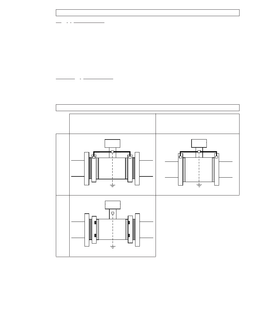
A
Teflon
®
PFA liner. For DN 25 - 150 and
1” - 6” meter sizes, additional gaskets
between measuring tube and
grounding rings or pipe flanges are not
required.
D2
Gaskets between grounding rings and
pipe flanges, not included in supply, to
be provided by customer.
Use Teflon-type flat gaskets to
DIN 2690/ANSI B 16.21,
deformable under pressure,
8 - 16 N/mm
2
/1160 - 2320 psi.
E / D1
Grounding rings, screwed to housing,
with inserted gaskets D1,
special O-rings.
FE
Functional ground, conductor
≥
4 mm
2
Cu/AWG 10.
R
Pipeline
RF
Pipe flanges
V
Interconnecting wires, bolted to
housing.
Y
Terminal box or signal converter.
Compact systems
Metal pipelines,
with or without internal coating,
and plastic pipelines
grounding with grounding rings
Metal pipelines,
not internally coated
grounding without grounding rings
DN 25 - 150 / 1” - 6”
DN 10 - 15 /
3
/
8
” -
1
/
2
”
R
R
V
V
RF
RF
D2
D2
E
E
A
A
R
R
RF
RF
D2
D2
E/D1
E/D1
A
A
FE
FE
R
R
V
V
RF
RF
FE
A
A
Grounding diagrams
Y
Y
Y