KROHNE ECOFLUX IFS 1000 EN User Manual
Page 7
7
5
Installation in the pipeline
•
Installation material, refer to table on page 3.
•
Pipe flanges and operating pressure,
refer to table on page 3.
•
Pipe flange spacing (fitting dimension)
1)
Dimensions including grounding rings
2)
No gasket required between measuring tube and pipe flanges, seal provided
by PFA liner on the flanges
s
Thickness of gasket D2 between grounding rings and pipe flanges, not
included with flowmeter, to be provided by customer. Use Teflon-type gaskets,
deformable under pressure, to DIN 2690/ANSI B 16.21,
8 - 16 N/mm
2
/1160 - 2320 psi.
•
High-temperature pipelines
Where process temperatures exceed 100 °C/212 °F, provide for facilities to
compensate for longitudinal expansion on heat-up of the pipeline.
For short pipelines use resilient gaskets and
for long pipelines install flexible pipe elements (e.g. elbows).
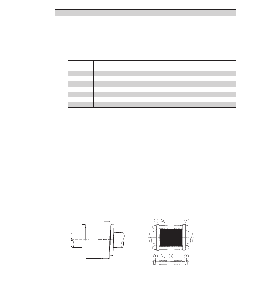
•
Position of flanges
• Arrangement of centering sleeves
Install flowmeter in line with the pipe
1 washer
axis. Pipe flange faces must be
2 centering sleeve
parallel to each other,
3 stud bolt
max. permissible deviation:
4 hex. nut
L
max
- L
min
≤
0,5 mm
≤
0.02”
L
max
L
min
Nominal size to . . .
Space between pipe flanges
DIN 2501
ANSI
Installation with
Installation without
and JIS
B 16.5
grounding rings 1)
grounding rings 2)
DN 10, 15
3
/
8
”,
1
/
2
”
2 x s + 68 mm
(2 x s + 2.68”)
–
–
DN 25
1
2 x s + 60 mm
(2 x s + 2.38”)
54 mm
(2.13”)
DN
40
1
1
/
2
”
2 x s + 84 mm
(2 x s + 3.31”)
78 mm
(3.07”)
DN
50
2
2 x s + 106 mm
(2 x s + 4.17”)
100 mm
(3.94”)
DN 80
3
2 x s + 156 mm
(2 x s + 6.14“)
150 mm
(5.91”)
DN 100
4
2 x s + 206 mm
(2 x s + 8.11”)
200 mm
(7.87”)
DN 150
6
2 x s + 206 mm
(2 x s + 8.11”)
200 mm
(7.87”)