KROHNE ECOFLUX IFS 1000 EN User Manual
Page 3
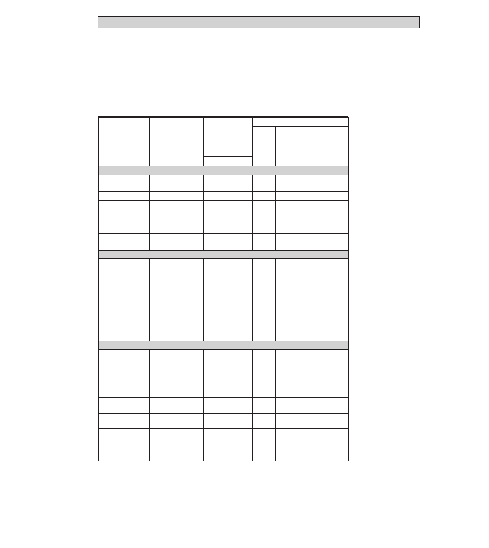
. . . DIN 2501 (BS 4504)
DN 10-15 1)
PN 16/PN 40
≤
16
≤
230
–
S
4
x
M12
DN 25
PN 16/PN 40
≤
16
≤
230
S
O
4
x
M12
DN 40
PN 16/PN 40
≤
16
≤
230
S
O
4
x
M16
DN 50
PN 16/PN 40
≤
16
≤
230
S
O
4
x
M16
DN 80
PN 16/PN 40
≤
16
≤
230
S
O
4
x
M16
DN 100
PN 16
≤
16
≤
230
S
O
8
x
M16
PN 40
8
x
M20
DN 150
PN 16
≤
16
≤
230
S
O
8
x
M20
PN 40
8
x
M24
. . . ANSI B 16.5
3
/
8
”-
1
/
2
” 1)
150/300 lb
≤
16
≤
230
–
S
4
x
1
/
2
”
1”
150/300 lb
≤
16
≤
230
S
O
4
x
1
/
2
”
1
1
/
2
”
150/300 lb
≤
16
≤
230
S
O
4
x
5
/
8
”
2”
150 lb
≤
16
≤
230
S
O
4
x
5
/
8
”
300 lb
8
x
5
/
8
”
3”
150 lb
≤
16
≤
230
S
O
4
x
5
/
8
”
300 lb
8
x
5
/
8
”
4”
150/300 lb
≤
16
≤
230
S
O
8
x
5
/
8
”
6”
150 lb
≤
16
≤
230
S
O
8
x
3
/
4
”
300 lb
12
x
3
/
4
”
. . . JIS
DN 10-15 1)
10 K
≤
07
≤
100
–
S
4
x
M12
20 K
≤
14
≤
200
4
x
M12
DN 25
10 K
≤
07
≤
100
S
O
4
x
M12
20 K
≤
14
≤
200
4
x
M16
DN 40
10 K
≤
07
≤
100
S
O
4
x
M12
20 K
≤
14
≤
200
4
x
M16
DN 50
10 K
≤
07
≤
100
S
O
4
x
M12
20 K
≤
14
≤
200
8
x
M16
DN 80
10 K
≤
07
≤
100
S
O
8
x
M12
20 K
≤
14
≤
200
8
x
M20
DN 100
10 K
≤
07
≤
100
S
O
8
x
M12
20 K
≤
14
≤
200
8
x
M22
DN 150
10 K
≤
07
≤
100
S
O
8
x
M16
20 K
≤
14
≤
200
12
x
M22
3
Nominal size
measuring
tube and
pipe
flanges
Pressure
rating or
flange class
of pipe flanges
Max.
allowable
operating
pressure
bar
psig
Supply scope S=standard O=option
excl.
grounding
rings
2)
incl.
grounding
rings
3)
Standard with
centering sleeves
(optionaly with stud
bolts, see below for
type and number
1)
For DN 10 and
3
/
8
” sizes, use DN 15 or
1
/
2
” pipe flanges.
2)
Ground connecting wires V screwed to housing, supplied without gaskets.
3)
DN 10 - 15 and
3
/
8
” -
1
/
2
”: grounding rings E with inserted D1 gasket, screwed to housing.
D2 gaskets between grounding rings and pipe flanges not included with flowmeter, to be provided by customer.
Use Teflon-type gaskets to DIN 2690/ANSI B 16.21, deformable under pressure, 8 - 16 N/mm
2
/1160 - 2320 psi.
DN 25 - 150 and 1” - 6”: grounding ring E (option) supplied loose, ground connecting wires V
screwed to housing, gaskets not included in supply.
For arrangement of gaskets and connection of wires V, see Section 7 “Grounding“.
Items included with supply
IFS 1000 F
primary head
•
primary head
in the size as ordered
•
certificate of calibration data
•
installation material as specified
in the following table
•
installation instructions
IFM 1010 K and IFM 1080 K
compact flowmeters
•
compact flowmeter
in the size as ordered
•
certificate of calibration data
•
installation material as specified
in the following table
•
installation instructions
•
installation and operating instruc-
tions for the signal converter