Safety-related characteristics – KROHNE TT 51 SERIES EN User Manual
Page 16
7
SAFETY-RELATED CHARACTERISTICS
16
TT 51 SERIES
www.krohne.com
09/2010 - 4000869801 - AD TT 51 SIL R01 en
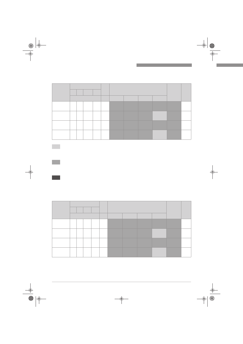
Single RTD 4w sensor
Dual RTD 4w sensor with activated sensor drift monitoring (only for TT 51 R SIL versions); in
preparation
Failure category
SFF PFD
avg
at T
proof
=
PFH
SIL AC
λ
SD
λ
SU
λ
DD
λ
DU
[FIT]
[%]
1 year
2 years
5 years
10 years
Close
coupled low
stress
0
146 436
43
93.1
2.16E-04
4.02E-04
9.62E-04
1.89E-03
4.30E-08
SIL 2
Close
coupled high
stress
0
146 1338
90
94.2
4.62E-04
8.52E-04
2.02E-03
3.97E-03
9.00E-08
(SIL 2)
Extension
wires low
stress
0
146 883
45
95.8
2.36E-04
4.31E-04
1.024E-03
1.99E-03
4.50E-08
SIL 2
Extension
wires high
stress
0
146 10288
140
98.6
9.15E-04
1.52E-03
3.34E-03
6.38E-03
1.40E-07
(SIL 2)
The boxes marked in light grey in the following tables mean that the calculated PFD
avg
and/or
PFH values are within the allowed range for SIL 2 according to table 2 / 3 of IEC 61508-1 but do not
fulfill the requirement to not claim more than 35% of this range, i.e. to be better than or equal to
3.50E-03 respectively 3.50E-07 1/h.
The boxes marked in medium grey mean that the calculated PFD
avg
and PFH values are within the
allowed range for SIL 2 according to table 2 / 3 of IEC 61508-1 and do fulfill the requirement to not
claim more than 35% of this range, i.e. to be better than or equal to 3.50E-03 respectively
3.50E-07 1/h.
The boxes marked in dark grey indicate that the PFD
avg
respectively the PFH values do not fulfill
the requirements for SIL 2 of table 2 / 3 of IEC 61508-1.
Failure category
SFF PFD
avg
at T
proof
=
PFH
SIL AC
λ
SD
λ
SU
λ
DD
λ
DU
[FIT]
[%]
1 year
2 years
5 years
10 years
Close
coupled low
stress
0
Close
coupled high
stress
0
Extension
wires low
stress
0
Extension
wires high
stress
0
.book Page 16 Thursday, September 9, 2010 4:19 PM