Profibus settings, 3 menu c, setup – KROHNE MFC 300 Profibus User Manual
Page 35
PROFIBUS SETTINGS
5
35
MFC 300
www.krohne.com
07/2014 - 4001086802 - AD MFC 300 PROFIBUS R02 en
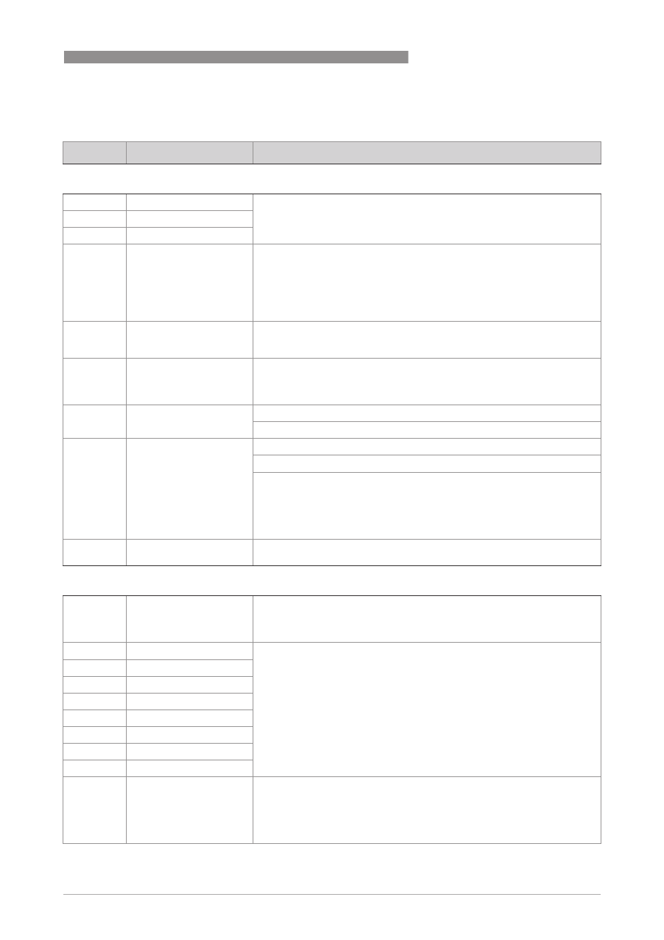
5.3 Menu C, Setup
No.
Function
Settings / descriptions
C4 I/O Totaliser
C4.1
FB4 Totaliser 1
Set function of Totaliser _
_ stands for 1, 2, 3 (= Totaliser 1, 2, 3)
C4.2
FB5 Totaliser 2
C4.3
FB6 Totaliser 3
C4._.1
Totaliser Function
Select:
Absolute Total (counts positive and negative values) /
Incremental Total (counts only the positive values) /
Decremental Total (counts only the negative values) /
Stop Totaliser (totaliser is stopped, no counting) /
All As Positive (neg. input will be multiplied with -1.0) /
All As Negative (pos. values will be multiplied with 1.0)
C4._.2
Measurement
Select:
Volume Flow / Mass Flow / Contentration Total 1 / Contentration Total 2 /
Conc. volume flow 1 / Conc. volume flow 2
C4._.3
Preset Value
Predefines a threshold (using high low limit value of the totaliser affected;
the THRESHOLD bit will be set in the long status information bytes of the
interface if the actual value of the totaliser is outside these limits. This can
be also used for a status output.
C4._.4
Reset Totaliser
The current value of the totaliser can be set to zero.
Select: No / Yes (reset totaliser 1…3)
C4._.5
Error Behaviour
Defines the behaviour of this function block in case of errors.
Select: hold meas. value / ignore error / stop totaliser
hold meas. value:
hold meas. value:
hold meas. value:
hold meas. value: Totalization is continued based on the last incoming value
with good status before the first occurrence of bad status.
ignore error:
ignore error:
ignore error:
ignore error: Totalization is continued using the input values despite the bad
status. The status is ignored.
stop totaliser:
stop totaliser:
stop totaliser:
stop totaliser: Totalization is stopped during occurrence of bad status of
incoming values.
C4._.6
Information
Serial no. of the I/O board, software version no. and production date of the
circuit board will be displayed
C5 I/O PROFIBUS
C5
I/O PROFIBUS
Using the menu functions mentioned below you will be able to control
basically the five analog input blocks of this PROFIBUS device. These eights
menus are identical so they are grouped together and their functions are
described in one go.
C5.1
FB1 Analog Inp.
There are 8 analog input blocks.
_ stands for the 8 analog input blocks: FB1 (_ = 1), FB2 (_ = 2), FB3 (_ = 3),
FB7 (_ = 4), FB8 (_ = 5), FB9 (_ = 6), FB10 (_ = 7), FB11 (_ = 8),
C5.2
FB2 Analog Inp.
C5.3
FB3 Analog Inp.
C5.4
FB7 Analog Inp.
C5.5
FB8 Analog Inp.
C5.6
FB9 Analog Inp.
C5.7
FB10 Analog Inp.
C5.8
FB11 Analog Inp.
C5._.1
Measurement
Select measurement for the analog input blocks:
Mass Flow / Density / Temperature / Concentration 1 / Concentration 2 /
Conc. mass flow 1 / Conc. mass flow 2 / Conc. volume flow 1 / Conc. volume
flow 2 / Sensor Deviation / Sensor Average / Drive Energy / Tube Frequency /
Tube Strain / Inner Cylinder Strain / Flow Velocity / Volume Flow /
Electronics Temperature / Supply