KROHNE CORIMASS MFC 85 Interface EN User Manual
Page 8
8
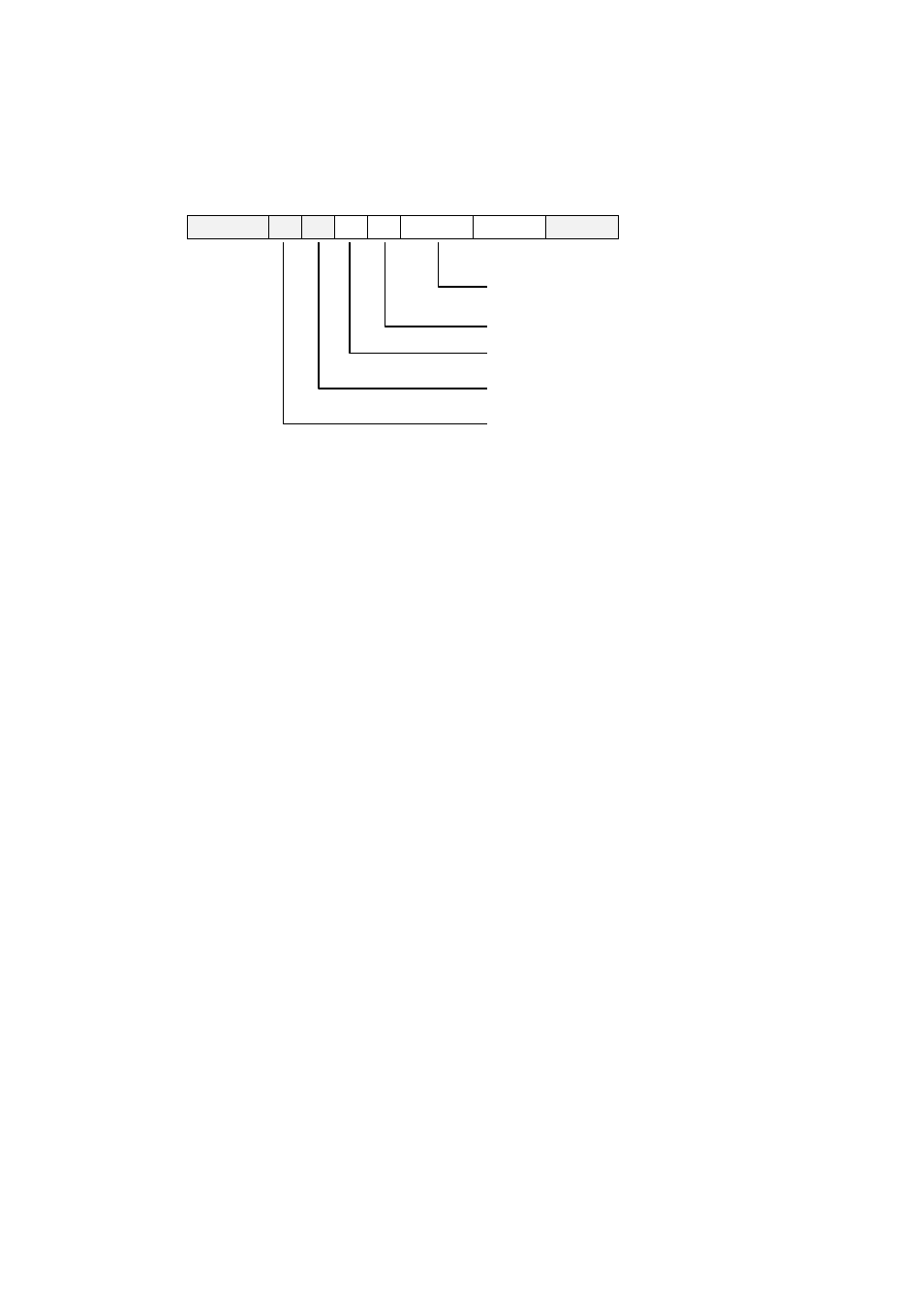
The structure of these messages can be seen in the figure below. In multi-drop mode this can
accommodate the addresses for several field devices and terminals.
Structure of a HART
®
message
Preamble
SD
AD
CD
BC
Status
Data
Parity
Field device and communication
status (ONLY from field device to
master)
Byte count
HART instruction
Display terminal and field device
addresses
Start character
The HART message structure offers a high degree of data integrity
A specific size of operand is required to enable the field device to carry out the HART
instruction. The byte count indicates the number of subsequent status and data bytes.
Layer 2 improves transmission reliability by adding the parity character derived from all the
preceding characters; each character also receives a bit for odd parity.
The individual characters are:
1 start bit
8 data bits
1 bit for odd parity
1 stop bit
Layer 7, the Application layer, brings the HART instruction set into play. The master sends
messages with requests for specified values, actual values and any other data or parameters
available from the device. The field device interprets these instructions as defined in the
HART protocol. The response message provides the master with status information and data
from the slave.
To make interaction between HART compatible devices as efficient as possible, classes of
conformity have been established for masters, and classes of commands for slaves. There
are six classes of conformity for a master as seen in the figure below.