KROHNE CORIMASS MFC 85 Interface EN User Manual
Page 26
26
3.1
Bus termination and Biasing Resisters
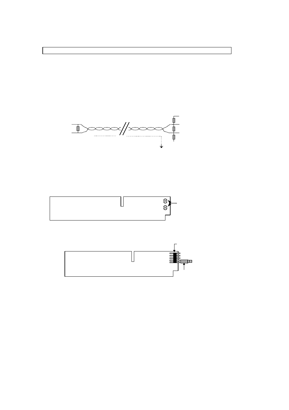
For proper operation of Modbus in half duplex mode in single or multi-drop communication, it
is recommended that a termination resistor (typically 120 ohm) is applied to both ends of the
data line. The simplest form of termination is line to line resistor across the differential input.
In RTU mode the Modus protocol requires quite periods on the communications bus for
synchronisation. It is therefore important that the Modbus is not allowed to ‘float’, i.e.
unreferenced to 0V, as this could lead to spurious signals due to noise pick-up. It is therefore
necessary to employ biasing resistors at one point on the bus network as shown in figure 3.
4 (TX-/RX-)=A
TX/RX
TX/RX
4.1 (TX+/RX+)=B
120R
150R
MFC 081/085
converter
4.2 (+5 V)
390R
390R
Screened twisted pair cable
5. (OV)
Fig. 3
For Ex instruments the termination resistor has to be inside the pressure tight section of the
housing or other suitable enclosure. For convenience terminating and biasing resistors are
already supplied on the RS 485/Modbus module. These can be enabled by soldering the two
solder pads together
(Fig. 3) or enabling the jumper which is supplied on modules of a later design. (Fig. 4).
Fig. 4
Fig. 5
OFF
Termination
RS 485
Module
S1
90
°
Pin header
Shorting link
ON
Termination
Solder pads
to be joined
RS 485
Module