Analog transmitter, 3 electrical connections, 1 ex i analog transmitter – KROHNE BM 26 BASIC-ADVANCED ATEX EN User Manual
Page 19
ANALOG TRANSMITTER
3
19
BM 26 BASIC/ADVANCED
www.krohne.com
12/2011 - 4000347102 - AD ATEX BM 26 Bas-Adv R02 en
3.3 Electrical connections
3.3.1 Ex i analog transmitter
• Use the electrical connection procedure in the Handbook.
• If possible, use galvanically-isolated equipment.
• Supply the Ex i equipment connected to the analog transmitter. Use only certified intrinsically-
safe equipment.
• Connect only to separate certified, intrinsically-safe circuits. Make sure that the electrical
circuit characteristics are not more than the values that follow:
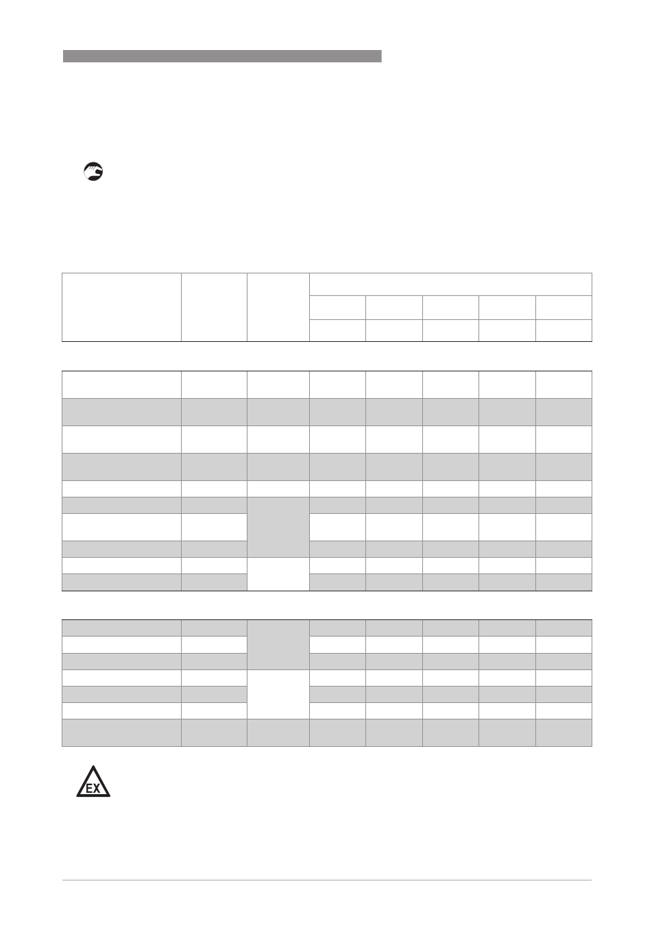
Maximum electrical circuit characteristics of converter modules for the analog transmitter
Module output
Converter
designation
Marking
Electrical circuit characteristics
U
i
I
i
P
i
C
i
Li
[V]
[mA]
[W]
[nF]
[µH]
Conventional intrinsically-safe systems
4...20 mA
xF45xB1xx
II 1 G Ex ia
IIC T4…T6
30
100
0.9
1
0
4...20 mA (PR)
xF45xV1xx
II 1 G Ex ia
IIC T4 or T6
30
120
0.84
1
10
4...20 mA + HART®
xF45xC1xx
II 1 G Ex ia
IIC T4...T6
30
100
0.9
1
1000
4...20 mA + HART® (PR)
xF45xW1xx
II 1 G Ex ia
IIC T4 or T6
30
150
0.84
1
10
4...20 mA + indicator
xF45xE1xx
II 1 G Ex ia
IIC T5
30
100
0.9
21
0
4...20 mA + HART® +
indicator
xF45xF1xx
30
100
0.9
21
1000
FF (PR)
xF45xD1xxxx
II 1 G Ex ia
IIC T4…T6
30
120
0.84
2
1
PROFIBUS PA (PR)
xF45xX1xxxx
30
300
1.3
2
1
FISCO intrinsically-safe systems
FF (PR)
xF45xD1xxxx
II 1 G Ex ia
IIC T4…T6
17.5
250
2
2
1
PROFIBUS PA (PR)
xF45xX1xxxx
15
Any
Any
2
1
FF (PR)
xF45xD1xxxx
II 2 G Ex ib
IIC T4…T6
17.5
Any
Any
2
1
PROFIBUS PA (PR)
xF45xX1xxxx
30
250
5.32
2
1
PROFIBUS PA
xF45xA1xxxx
II 1 G Ex ia
IIC T4…T6
17.5
380
5.32
1
10
DANGER!
Type type of module will have also have an affect on the maximum ambient temperature. For
more data, refer to Operating conditions on page 18
.