Re 6 shows – KEPCO RKW 1500W Series Operator Manual User Manual
Page 9
228-1503 REV 4 060110
7
low level very quickly when the power supply is at a low load condition. Remote sensing cannot be
used for parallel operation, series operation and for remote voltage control.
RESISTANCE: Use a shielded wire 6.6 feet (2m) maximum in length, for connection (of REF, RV,
and –S terminals) to the trimmer control. Connect the external trimmer as shown in Figure 7 (A).
Suggested value for the trimmer control is 5K ohms). With the external trimmer control at its max-
imum clockwise position, set the output voltage to the desired maximum value by adjusting Vadj
clockwise. The value should range from 0 to 120% of Eo nominal (from 0 to 110% for the 48-volt
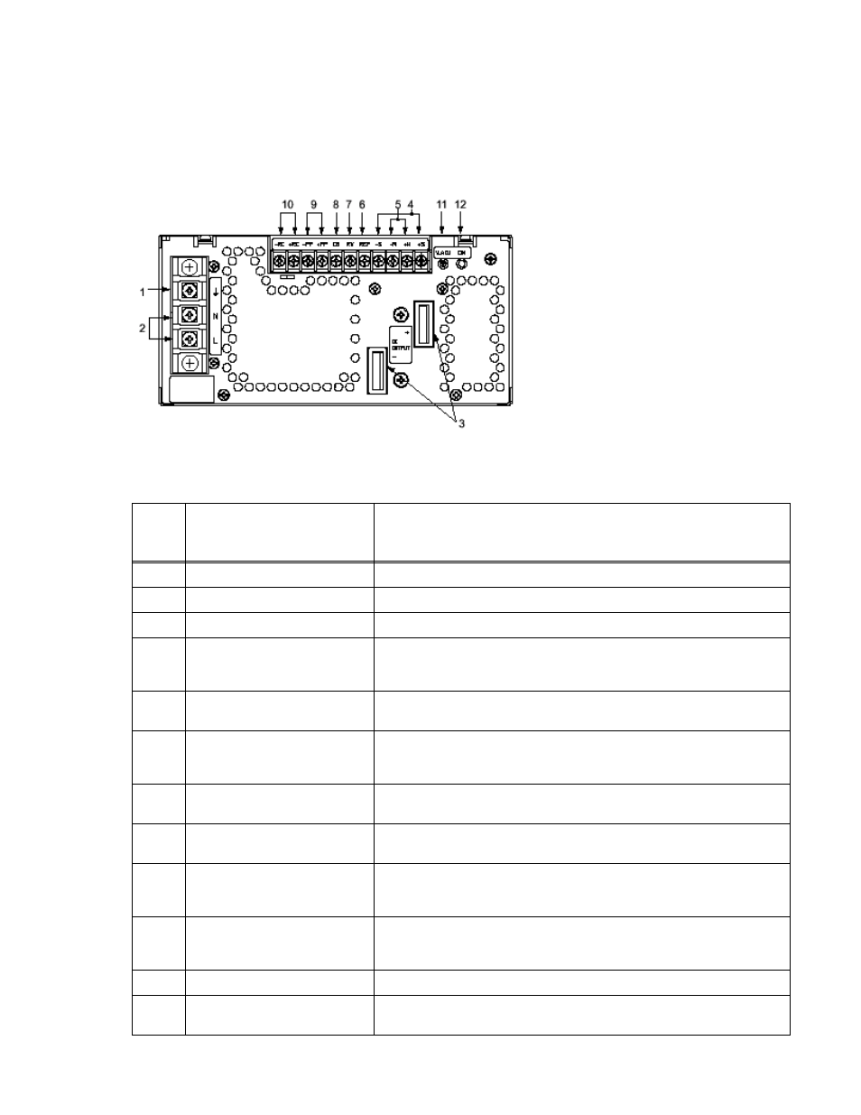
FIGURE 6. LOCATIONS OF OPERATING CONTROLS, INDICATORS AND TERMINALS
TABLE 3. FUNCTION OF CONTROLS, INDICATORS AND TERMINALS
FIG. 6
INDEX
NO.
CONTROL, INDICATOR,
TERMINAL
FUNCTION
1
Frame Ground (earth)
Connect to earth ground. This terminal is connected to the case.
2
A-C Input (L, N)
Connect to AC: 100 to 240V input line.
3
D-C Output (+, –)
Connect to load (see Figure 8).
4
Sense (+S, –S)
Used to compensate for voltage drop in the connecting lines from the output ter-
minal to a load; they are connected to ±M terminals for local sensing (see Figure
8).
5
+M, –M Output Voltage Monitor
Used to connect output measurement device. Normallly connected to sense ter-
minals (S+, S–) via shorting link for local sensing
6
Output Voltage Reference (REF)
Using REF terminal (together with the RV terminal) allows all the output voltages
of slave power supplies to be controlled by one voltage adjustment of a master
power supply (normally connected to the RV terminal with a metal shorting link).
7
Output Voltage Adjust (RV)
This terminal (together with the REF terminal) is used for remotely controlling
output voltage (see PAR. 4.2).
8
Current Balance (CB)
This terminal is used when several power supplies are connected in parallel (see
PAR. 6.3).
9
Power Failure (PF)
These terminals output an open logic signal if output voltage drops to 80 % or
lower of a set voltage, or if output voltage is shut down due to overvoltage or
overcurrent protection, fan speed failure, or overheating. (see Figure 3).
10
Remote ON-OFF (+RC, –RC)
Output is turned ON-OFF by opening-shorting the RC terminals (output OFF
when open). RC terminals are isolated from input and output terminals. Nor-
mally, ±RC terminals are shorted with a metal shorting link (see PAR. 4.3).
11
Output Voltage Trim Adjust (Vadj)
Adjusts output voltage.
12
Output Voltage On indicator
(green)
Green LED lights when output voltage is present.
NOTE Unit is shipped with shorting links
(not shown) connecting +RC to –RC (see
PAR. 4.3) and REF to RV (see PAR. 4.2)
and with local sensing links installed (con-
nects +M to +S and –M to –S) (see PAR.
6.1). See PAR. 6.2 for remote sensing.