Figure 7. connections for remote voltage control, 3 remote turn on-turn off, 1 overvoltage and overtemperature protection – KEPCO RKW 1500W Series Operator Manual User Manual
Page 10: 2 overcurrent protection, Connections for remote voltage control, Re 7 (a), R. 4.3), Ba a
8
228-1503 REV 4 060110
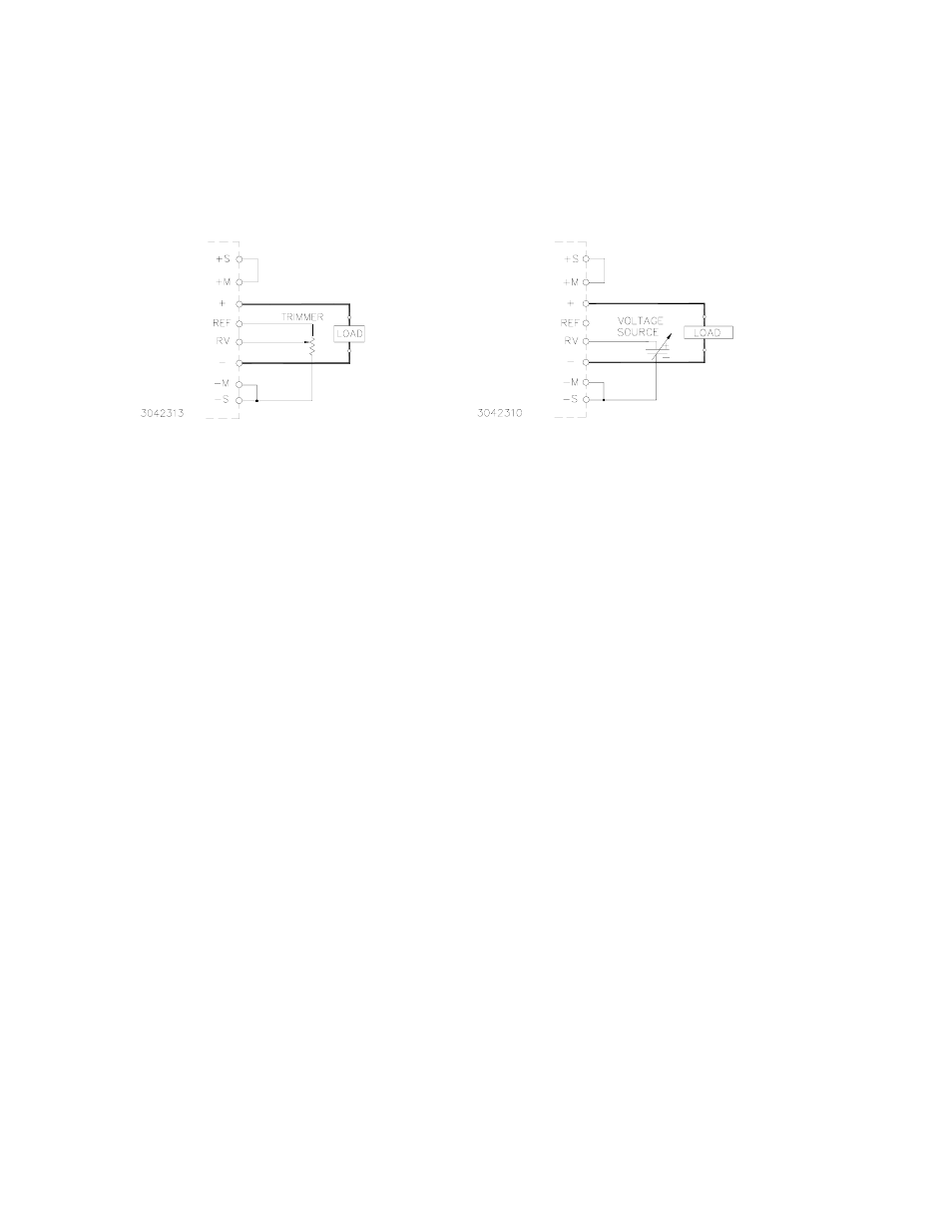
model, and for the 3-volt model). The remote voltage control may not be able to go down to zero
volts because of the residual resistance of the potentiometer (could be about 10%).
VOLTAGE. By adjusting an external 0-6V voltage source (0-5.5V for the 48-volt model, the 3.3-volt
model can be adjusted to 3.6V) from minimum to maximum, the maximum output voltage can be
adjusted from 0 to 120% (V) (for the 48 volt models 110%). Remove the shorting link between the
REF and RV terminal. Connect the voltage source across the RV and (–)S terminals as shown in
Figure 7 (B).
FIGURE 7. CONNECTIONS FOR REMOTE VOLTAGE CONTROL
4.3
REMOTE TURN ON-TURN OFF
When power is ON at the source, the output may be turned ON or OFF with the remote control
feature using the ±RC terminals (see Figure 6). These terminals accept a logic level (2.4V to 24V
"high" and 0.0 to 0.4V "low"), or a contact closure. When the ±RC terminals are open, using either
a mechanical switch or a high level logic signal, the RKW 1500W output is cut OFF. When the RC
terminals are shorted, the output returns to within specifications. At low level logic, the maximum
source current is 1.6mA and at high level the sink current is 1.0mA. The RC terminals must
remain shorted if remote ON-OFF is not used. The RC terminals are isolated from both the AC
input and DC output terminals.
5.
ALARM FUNCTIONS
5.1
OVERVOLTAGE AND OVERTEMPERATURE PROTECTION
When the output voltage of the RKW 1500W Power Supply increases beyond the specified values
(see Table 1), the output is cut OFF and the fan turns OFF. Overvoltage setting tracks output volt-
age up to maximum specified in Table 1. To restart (reset) the unit, remove AC input power, wait
about 40 seconds, then reconnect AC input power; or open the RC terminals and then reclose the
terminals.
When the internal temperature of the RKW 1500W Power Supply increases beyond the specified
values (see Table 1), the output is cut OFF and the fans turn OFF. The restart cycle (Power ON)
should not begin until the temperature returns to within specifications. To restart (reset) the unit,
remove AC input power, wait about 40 seconds, then reconnect AC input power. The power sup-
ply cannot be reset by using the remote ON-OFF feature unless the power supply is first shut
down for about 40 seconds and then turned on again.
The alarm circuit is a diode transistor optical coupler. The transistor is normally conducting. When
the alarm is activated, the transistor cuts off and the collector emitter circuit is open (see Figure 2)
5.2
OVERCURRENT PROTECTION
The output characteristic of the power supply is a square type, and the unit is set to shut down if
output current exceeds specifications (see Table 1) for more than 30 seconds. To restart (reset) the
unit, remove AC input power, wait about 40 seconds, then reconnect AC input power. or open the
RC terminals and then reclose the terminals. (see PAR. 4.3).
B
A
A