Optical coupler output alarm circuit – KEPCO RKW 1500W Series Operator Manual User Manual
Page 6
4
228-1503 REV 4 060110
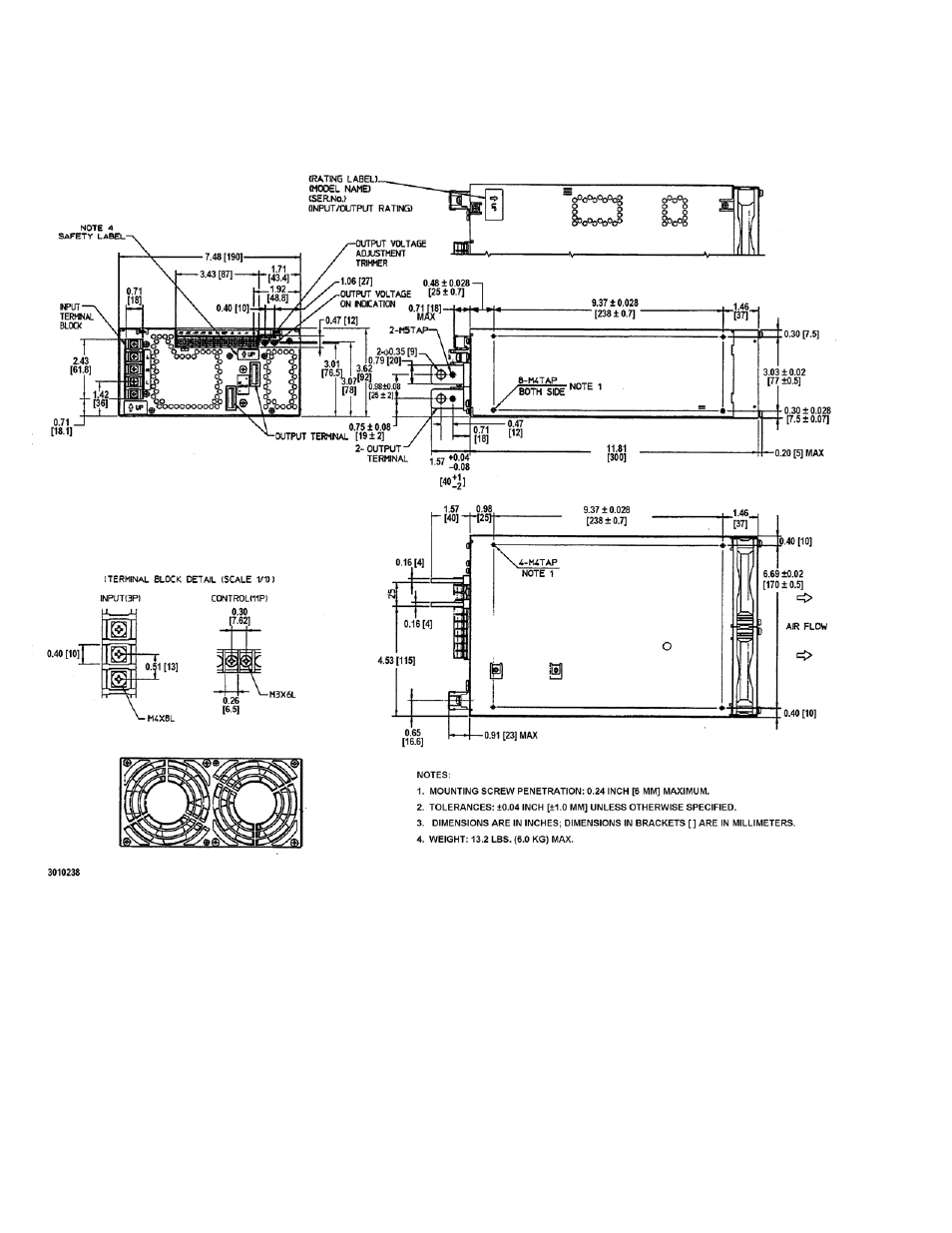
FIGURE 1. MECHANICAL OUTLINE DRAWING OF THE RKW 1500W POWER SUPPLY
3.
OPTICAL COUPLER OUTPUT ALARM CIRCUIT
When the output voltage falls to less than about 80 percent of programmed output voltage the
alarm is activated (a high logic level will appear at the ±PF terminals). The default state of the
alarm is logic low. The sink current is 50mA maximum, the maximum collector to emitter satura-
tion voltage is 0.40 Volts, and the collector to emitter voltage is 40 volts maximum. The PF ter-
minals are isolated from the AC and DC output input terminals. Insulation resistance between
the PF terminals and the AC input terminals is the same as the insulation resistance between
the input and output. Insulation resistance between the PF terminals and the output terminals is
the same as the insulation resistance between the output and ground.
- ABC-DM SERIES (96 pages)
- ATE (all models) QUICK START GUIDE (8 pages)
- SN 488-D (16 pages)
- SN 488-D (94 pages)
- SN 488-D (14 pages)
- BHK-MG 200W (Full Rack) Series (152 pages)
- BHK-MG 40W (Half Rack) Series (148 pages)
- BIT 232 (72 pages)
- BIT 4882 (56 pages)
- BIT 4886 Quick Start Guide (4 pages)
- BIT 4886 Operator Manual (92 pages)
- BOP 100W, 200W, 400W (M, D) Quick Start Guide (8 pages)
- BOP 20-5ML Modification Sheet (1 page)
- BOP 20-10MC Modification Sheet (2 pages)
- BOP 36-6MC Modification Sheet (2 pages)
- BOP 100-2MC Modification Sheet (2 pages)
- BOP 50-4MC Modification Sheet (2 pages)
- BOP 100-2ML Modification Sheet (2 pages)
- BOP 72-3ML Modification Sheet (2 pages)
- BOP 50-4ML Modification Sheet (2 pages)
- BOP 36-6ML Modification Sheet (2 pages)
- BOP 20-10ML Modification Sheet (2 pages)
- BOP 72-6MC Modification Sheet (2 pages)
- BOP 36-12MC Modification Sheet (2 pages)
- BOP 20-20MC Modification Sheet (2 pages)
- BOP 100-4ML Modification Sheet (2 pages)
- BOP 72-6ML Modification Sheet (2 pages)
- BOP 50-8ML Modification Sheet (2 pages)
- BOP 36-12ML Modification Sheet (2 pages)
- BOP 20-20ML Modification Sheet (2 pages)
- BOP 1KW-MG Quick Start Guide (16 pages)
- BOP 1KW-MG Quick Reference Guide (2 pages)
- BOP 1KW-MG Operator Manual, Firmware Ver.4.12 and higher (196 pages)
- BOP 1KW-MG Operator Manual, Firmware Ver.4.08 to 4.11 (194 pages)
- BOP 1KW-MG Operator Manual, Firmware Ver.3.05 to 4.07 (194 pages)
- BOP 1KW-MG Operator Manual, Firmware Ver.2.48 to 3.04 (188 pages)
- BOP 1KW-MG Operator Manual, Firmware Ver.2.38 to 2.47 (188 pages)
- BOP 1KW-MG Operator Manual, Firmware Ver.2.01 to 2.37 (176 pages)
- BOP 1KW as Solar Device Tester Quick Start Guide (3 pages)
- BOP-GL 1KW Quick Start Guide (16 pages)
- BOP-GL 1KW Operator Manual Firmware Ver.3.05 and higher (168 pages)
- BOP-HV (48 pages)
- CA 26 (2 pages)
- CA 27 (2 pages)
- CA 29 (2 pages)