1 voltage adjustment, 2 remote voltage control, Mounting positions for the rkw 1500w power supply – KEPCO RKW 1500W Series Operator Manual User Manual
Page 8
6
228-1503 REV 4 060110
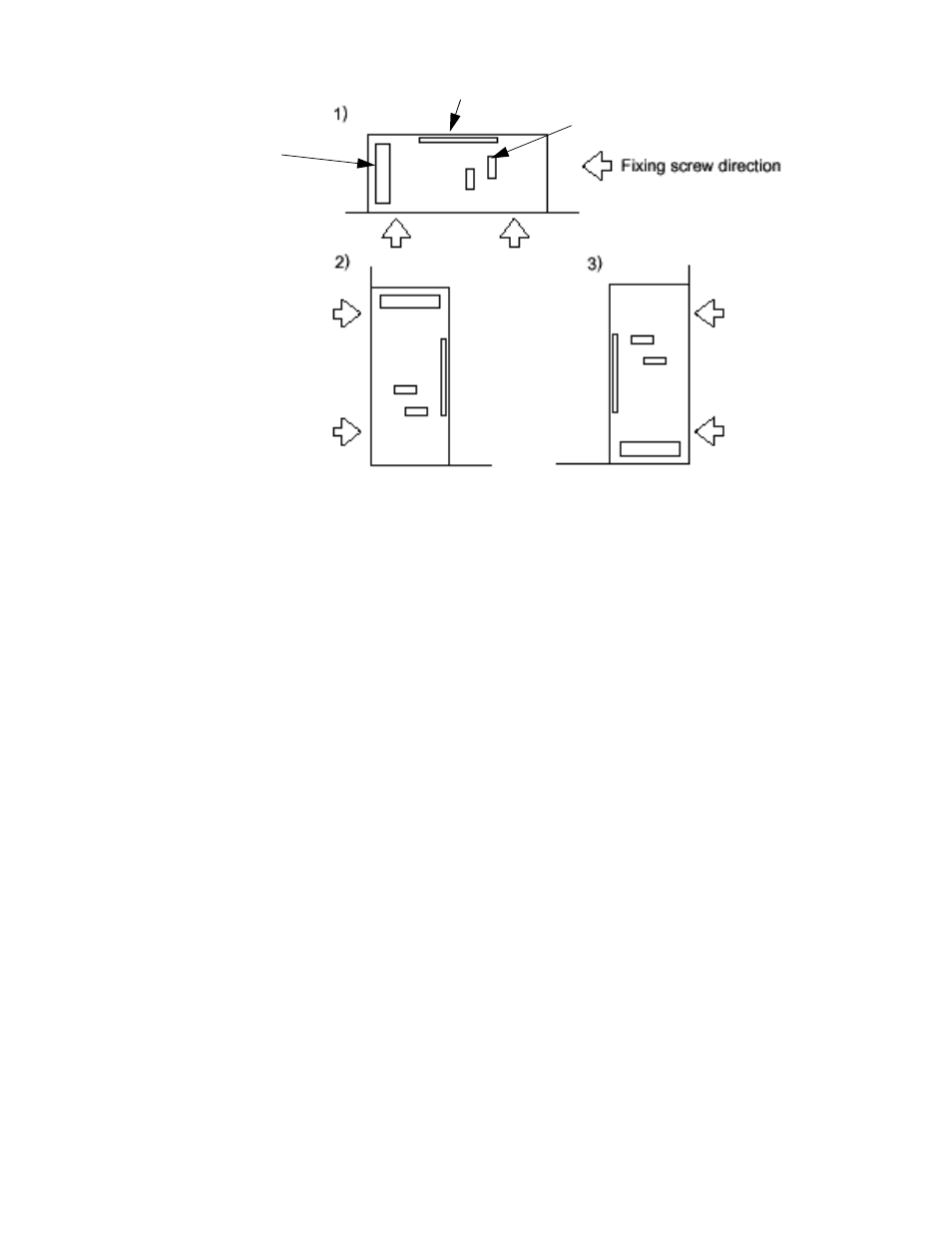
FIGURE 5. MOUNTING POSITIONS FOR THE RKW 1500W POWER SUPPLY
4.
OPERATION
Figure 6 shows the location of all operating controls and input/output terminals; Table 3 provides
an explanation of each. The unit is shipped with shorting links installed connecting the following
terminals: +RC to –RC and REF to RV, +M with +S and –M with –S (+M, –M to +S, –S connec-
tions provide local sensing).
NOTES:
1. +S and –S MUST be properly connected for the unit to operate. For local
sensing, leave local sensing links in place (refer to PAR. 6.1). For
remote sensing (at the load), refer to PAR. 6.2.
2. If remote ON/OFF is not being used, ±RC terminals must be connected
(use shorting link supplied) for unit to operate.
4.1
VOLTAGE ADJUSTMENT
Output voltage can be manually adjusted with the voltage adjustment control, Vadj (see Figure 6).
To adjust voltage, first place the unit under an operating load, then monitor the (+)S and (–)S
Sense terminals with a precision voltmeter and turn the voltage control to the desired operating
value. Refer to Table 1 for the recommended Adjustment Range of all the RKW 1500W Models.
4.2
REMOTE VOLTAGE CONTROL
The unit is shipped with a shorting link in place between RV and REF terminals. Removal of this
link allows the output voltage to be adjusted by either a trimmer pot (resistance) or by an external
variable voltage source across the RV terminal and –S terminal.
NOTE: Specifications are met when voltage is within adjustment range in Table 1. If remote
voltage control is not implemented, the shorting link between RV and REF must be in
place.
Use either local sensing (PAR. 6.1) or remote sensing (PAR. 6.2). It is possible that the overvolt-
age protection may be triggered if the output voltage is manually (using RV control) decreased to a
AC INPUT
TERMINAL
DC OUTPUT
BUS
SIGNAL TERMINALS
Maintain a 1.25 in. (30 mm)
min. distance between ven-
tilation holes, fan surface
and surrounding equipment
and install to provide heat-
outside air exchange