Calibration procedure, Figure 3. calibration set-up – KEPCO KT Series Accessories User Manual
Page 3
083107
228-0949 REV 6
3
KEPCO, INC. " 131-38 SANFORD AVENUE " FLUSHING, NY. 11355 U.S.A. " TEL (718) 461-7000 " FAX (718) 767-1102
http://www.kepcopower.com " email: [email protected]
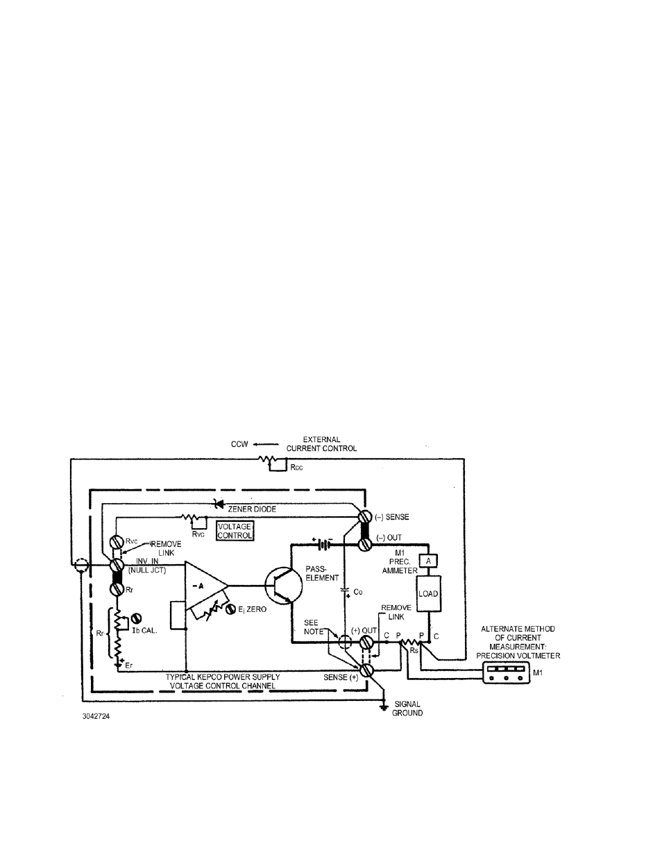
CALIBRATION PROCEDURE
The Kepco power supply, now converted to supply stabilized output current, can be calibrated by means of its built-in
I
b
CAL and E
io
ZERO controls and by adding a precision ammeter (or a voltmeter parallel to the sensing resistor) in
series with the load. If the power supply lacks the calibration controls, they may be added externally to most Kepco
power supplies. (Refer to your Kepco Instruction Manual). Connect the load, the calibrating instrument and the exter-
nal components as shown in FIG. 3. Proceed as follows:
1. Turn calibration set-up “on” and allow for a sufficient warm-up period. (Warm-up time depends on the envi-
ronmental temperature, the power supply output power and the effectiveness of the heat-sink on which the
external sensing resistor is mounted.)
2. Turn the external current control resistor (R
CC
) through its range to check for smooth operation over the
selected range. Set (R
CC
) to “zero ohms” (CCW).
3. Observe the calibrating meter (M1). Correct zero point by adjusting the built-in (or external) E
io
ZERO con-
trol.
4. Turn (R
CC
) to its maximum resistance position (CW). Observe M1. Correct maximum output current point by
adjusting the built-in (or external) I
b
CAL control.
5. Recheck “zero” point by repeating procedure described in steps 2 and 3 above.
NOTE: The limitation imposed by using a single sensing resistor and by parallel leakage paths inside the power
supply restrict the usable output current range, obtainable with the described method, to approximately
2% to 100% l
O
max. If current control over a wider range is desired, two or more ranges can be imple-
mented, each range requiring its own sensing resistor, calculated on the basis of a l-volt sensing voltage
at the maximum range current. For a power supply with a maximum rated output current of 50 amperes for
example, two sensing resistors (Model KT 1915 and Model KT 2330) would cover the ranges from 0.02
Ampere to 1 Ampere and from 1 Ampere to 50 Amperes. (See Table 1.)
.
FIGURE 3. CALIBRATION SET-UP
NOTE:
R
S
should be physically located as
close to the (+) output terminal of the
power supply as possible. In this
case, the link (+) OUT – (+) SENSE
CAN BE CLOSED and the connec-
tion (+) SENSE to terminal P of R
S
can be deleted. If R
S
must be
located some distance from the
power supply, the sensing connec-
tion as shown must be used (link
(+) OUT – (+) SENSE removed) and
the (+) terminal of the output capaci-
tor (C
O
must be internally recon-
nected from the (+) sensing to the
(+) output terminal.