KEPCO KT Series Accessories User Manual
Kepco, Accessory, Equipment
©2007, KEPCO, INC
1
Data subject to change without notice
228-0949 REV 6
I N S T R U C T I O N M A N U A L
KT
KEPCO
KEPCO, INC. " 131-38 SANFORD AVENUE " FLUSHING, NY. 11355 U.S.A. " TEL (718) 461-7000 " FAX (718) 767-1102
http://www.kepcopower.com " email: [email protected]
An ISO 9001 Company.
ACCESSORY
EQUIPMENT
CURRENT CONTROL RHEOSTAT
CURRENT SENSING RESISTORS
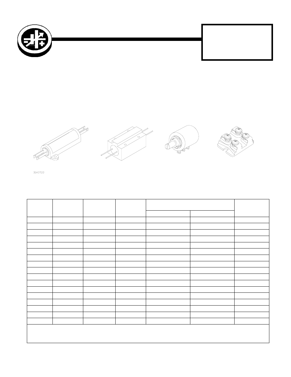
GENERAL DESCRIPTION (Refer to FIG’s 1 and 2)
Kepco Current Sensing and Control Resistors are precision, wire-wound components with low temperature coeffi-
cients. The 4-terminal current sensing resistor (R
S
) and the 10-turn current control rheostat (R
CC
) provide all the exter-
nal circuitry needed to convert a d-c voltage stabilizer into a d-c source supplying stabilized output current. The sensing
resistor (R
S
), placed in series with the load, provides a voltage drop proportional to the output current. The control
rheostat (R
CC
) is connected to supply feedback from the sensing resistor to the NULL JUNCTION (INVERTING
INPUT) of the power supply. In this manner, excellent current stabilization can be achieved over a minimum range of
2% to 100% of I
O
max. where I
O
max. is the selected maximum power supply output current. (Refer to FIG. 2). The cur-
rent sensing resistors can also be used for measuring the output current delivered by the power supply.
FIGURE 1. KEPCO CURRENT SENSING RESISTORS AND CONTROL RHEOSTAT
TABLE 1. KEPCO SENSING RESISTORS
MODEL
RESISTANCE
(OHMS)
TERMINATION
POWER
RATING (1)
RECOMMENDED OUTPUT CURRENT RANGE
BASED ON 1-VOLT SAMPLE
OUTLINE
DIMENSIONS
LOW
HIGH
KT 1915
1.0
LEADS
50W
0.02A
1A
SEE FIG. 4, A
KT 1385
0.667
LEADS
50W
0.03A
1.5A
SEE FIG. 4, A
KT 1399
0.5
LEADS
50W
0.04A
2A
SEE FIG. 4, A
KT 1386
0.333
LEADS
50W
0.06A
3A
SEE FIG. 4, A
KT 1598
0.2
LEADS
50W
0.01A
5A
SEE FIG. 4, A
KT 2356
0.1
LEADS
50W
0.2A
10A
SEE FIG. 4, A
KT 2713
0.01
LEADS
50W
N.A.
(2)
N.A.
(2)
SEE FIG. 4, A
KT 2537
0.0625
LEADS
100W
0.32A
16A
SEE FIG. 4, B
KT 2536
0.05
LEADS
100W
0.4A
20A
SEE FIG. 4, B
KT 2480
0.033
LEADS
100W
0.6A
30A
SEE FIG. 4, B
KT 2330
0.02
LEADS
100W
1A
50A
SEE FIG. 4, B
KT 2325
0.01
LEADS
100W
2A
100A
SEE FIG. 4, B
KT 2714
0.001
LEADS
100W
N.A.
(2)
N.A.
(2)
SEE FIG. 4, B
KT 3146
1
SCREW
30W
0.02A
1A
SEE FIG. 4, D
KT 3126
0.1
SCREW
30W
0.2A
10A
SEE FIG. 4, D
KT 3130
0.01
SCREW
30W
1A
50A
SEE FIG. 4, D
KT 3131
0.001
SCREW
30W
2A
100A
SEE FIG. 4, D
(1)
A suitable heatsink must be provided, See “INSTALLATION” paragraph.
Power Rating based on 275 °C max. hot spot temperature in 25 °C ambient, derate to 80% power in 71 °C ambient.
(2)
These sensing resistors are designed to provide a 0-200mV sample voltage for currents of 20A (KT 2713) and 200A (KT 2714) respectively.
Kepco Model KT 1304, 0-1000
Ω
1W at 65°C, 20 ppm max
See FIG. 4, C for dimensions.
CURRENT FEEDBACK CONTROL
TYPICAL 100W RESISTOR (LEADS)
TYPICAL 50W RESISTOR (LEADS)
TYPICAL 30W RESISTOR (SCREWS)
Document Outline
- GENERAL DESCRIPTION
- FIGURE 1. Kepco Current Sensing Resistors and Control Rheostat
- TABLE 1. Kepco Sensing Resistors
- SENSING RESISTOR SELECTION
- INSTALLATION
- INTERCONNECTIONS
- FIGURE 2. External Current Sensing and Control Using the Voltage Mode Amplifier
- CALIBRATION PROCEDURE
- FIGURE 3. Calibration Set-up
- FIGURE 4. Mechanical Outline Dimensions