Sensing resistor selection, Installation, Interconnections – KEPCO KT Series Accessories User Manual
Page 2
2
228-0949 REV 6
083107
KEPCO, INC. " 131-38 SANFORD AVENUE " FLUSHING, NY. 11355 U.S.A. " TEL (718) 461-7000 " FAX (718) 767-1102
http://www.kepcopower.com " email: [email protected]
SENSING RESISTOR SELECTION
The value of the sensing resistor (R
S
) is selected according to the desired output current range, such that a I-volt
sample is provided at the maximum output current (l
O
MAX):
INSTALLATION
The minimum required heat sink area for the listed power rating of the current sensing resistors is 144 square
inch, 1/4 in. thick aluminum (950 square centimeters, 0.5 centimeters thick). If the actual power dissipation
(MAXIMUM OUTPUT CURRENT TIMES ONE VOLT) exceeds one-tenth of the power rating, additional
cooling by means of an air stream or an oil-bath should be provided to keep the heat-rise in the sensing
resistor to a minimum. To minimize output ripple (“pick-up”) mount the sensing resistor assembly as close to
the power supply as practicable. Use shielded cable to connect the current control resistor to the null junction of
the power supply and connect the shield (single-ended) to the common signal ground.
INTERCONNECTIONS
The simplified connecting diagram (refer to FIG. 2) shows the electrical connection of the Sensing and Control
Resistors to a typical Kepco Power Supply. The nomenclature used in the diagram coincides with that used on all
Kepco Power Supplies. Refer to your Kepco Instruction Manual when in doubt about interconnections or terminal
designations.
NOTE: If the load must be protected from excessive compliance (output) voltage, a zener diode, rated to
conduct at the desired voltage, should be connected as shown in FIG. 2.
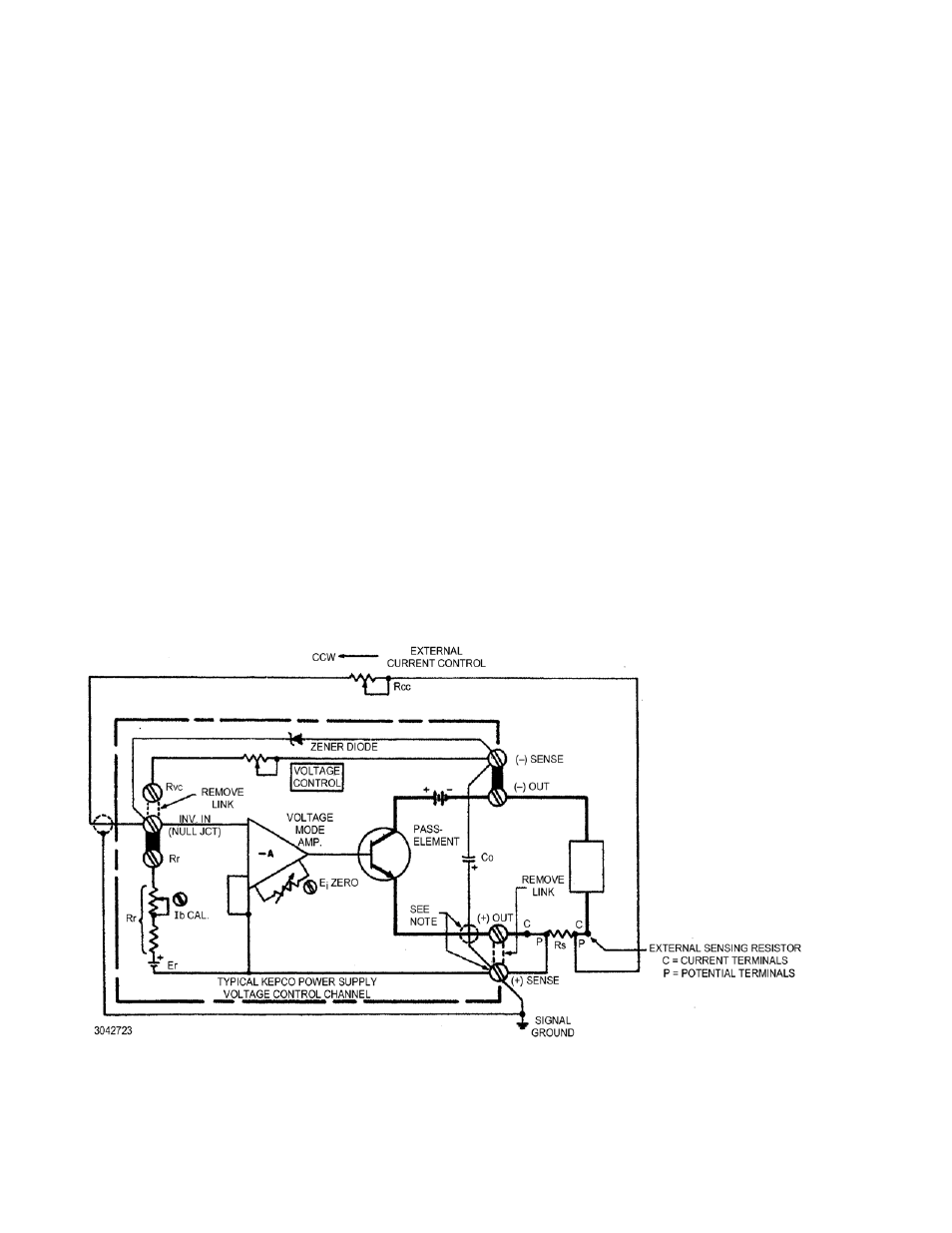
FIGURE 2. EXTERNAL CURRENT SENSING AND CONTROL USING THE VOLTAGE MODE AMPLIFIER
NOTE:
R
S
should be physically located as
close to the (+) output terminal of the
power supply as possible. In this
case, the link (+) OUT – (+) SENSE
CAN BE CLOSED and the connec-
tion (+) SENSE to terminal P of R
S
can be deleted. If R
S
must be
located some distance from the
power supply, the sensing connec-
tion as shown must be used (link
(+) OUT – (+) SENSE removed) and
the (+) terminal of the output capaci-
tor (C
O
must be internally recon-
nected from the (+) sensing to the
(+) output terminal.
RS
1 Volt
IOMax.
--------------------
=
(See Table 1 for values.)