E 2), E 2) from distribution board a – KEPCO KIT 219-0533, BOP 1000W Firmware Upgrade User Manual
Page 4
4
228-1644 REV 7
091611
KEPCO, INC. 131-38 SANFORD AVENUE FLUSHING, NY. 11355 U.S.A. TEL (718) 461-7000 FAX (718) 767-1102
http://www.kepcopower.com email: [email protected]
9. Pry out the PROM U24 using an IC extractor. Insert the hook, first into one slot and then the other, and gently
pry out the PROM. Place the PROM in the tube and close the tube.
10. Open the other end of the IC tube and remove the replacement PROM U24 from the tube.
11. Insert the PROM into the socket, insuring the dot on the chip is oriented as shown in Figure 1.
12. Reclose the IC tube. Remove wrist strap and disconnect it from the BOP chassis.
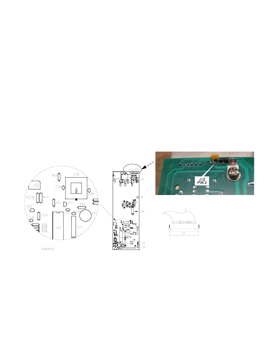
3.5 DISTRIBUTION BOARD A6A1 PROM REPLACEMENT (SEE FIGURE 2)
CAUTION: Note which screws do not use flat washers and tag for reassembly.
1. Perform this step for BOP 36-26MG only; for all other models, skip to step 2. For the BOP 36-28MG, this step
insures the front panel adjuster does not have erratic operation.
a. Remove screw in upper left hand corner of front panel securing A6A1 to the front panel.
b. Install the screw just removed through the lug of the capacitor assembly supplied, and reinstall the screw
(hand tight); refer to Figure 2, Detail A.
c. Solder the other end of the capacitor to pin 2 of J12 as shown in Figure 2, Detail A.
FIGURE 2. DISTRIBUTION BOARD A6A1 COMPONENT LOCATION
2. Remove seven screws, seven lockwashers and five flat washers securing the Distribution board A6A1 to the
front panel. Carefully separate the Distribution board A6A1 from the front panel. The PROM on the Distribution
board A6A1 is now accessible for replacement (it is not necessary to disconnect the ribbon cables between
the front panel and Distribution board A6) to replace the PROM.
3. Place Distribution board A6A1 on an ESD mat (if an ESD mat is not available, place the Distribution board on
the top cover) and locate PROM U9 (see Figure 2).
CAUTION: FAILURE TO USE THE ESD WRIST STRAP MAY DAMAGE THE PROM!
TO REASSEMBLE:
INSERT RIBBON CABLE INTO J4
(PUSH DOWN AT ARROWS IF NECESSARY).
DOWN
DOWN
DISTRIBUTION BOARD (FAR SIDE)
DETAIL A: CAPACITOR ASSEMBLY INSTALLATION
(BOP 36-28 ONLY)