Table 1. material required – KEPCO KIT 219-0533, BOP 1000W Firmware Upgrade User Manual
Page 2
2
228-1644 REV 7
091611
KEPCO, INC. 131-38 SANFORD AVENUE FLUSHING, NY. 11355 U.S.A. TEL (718) 461-7000 FAX (718) 767-1102
http://www.kepcopower.com email: [email protected]
3. Remove the top cover of the unit by removing 14 screws as follows: two at top of the front panel, four at each
side, (one towards the rear, three at the bottom) and four at the top of the rear panel.
4. Observe back of front panel-mounted circuit breaker. If a Printed Circuit Board is present, skip this step. If not,
tag and remove the four quick disconnect cables from circuit breaker.
5. Disconnect ribbon cable attached to Distribution board A6A1 (see Figure 1) going to Front End Control board
A4A3 connector J1.
6. Disconnect ribbon cable attached to Distribution board A6 going to Digital board A1J2.
7. Disconnect two 4-pin connectors (or, on some units one 4-pin and one 6-pin connector) (J12, J15, Figure 2),
and one 5-pin connector (J14, Figure 2) wired with twisted pairs from Distribution board A6. Pull on the twisted
pair where it enters the connector; if necessary, a screwdriver can be used to apply enough pressure to front
panel to slightly increase separation between front panel and Distribution board A6, enough for the connectors
to be removed.
CAUTION: Failure to pull the fan connector straight back can damage the connector.
8. Remove fan connector (J10, Figure 2) from Distribution board A6 by pulling connector straight back
CAUTION: Removing the outer screws first can result in damage to the front panel.
9. At the bottom of the chassis, first remove the two inner screws, then the two outer screws securing front panel
to chassis and separate front panel and Distribution board A6 from the chassis.
10. For units without lug wires, carefully pull the front panel straight back from the chassis to disengage the circuit
breaker pins and separate the front panel from the chassis
11. Pry black cover off front panel ADJUST knob. Then remove ADJUST knob by releasing the nut.
3.4 DIGITAL BOARD A1 COMPONENT REPLACEMENT (SEE FIGURE 1)
NOTE: Steps 1 and 2 can be skipped if brief trigger pulses (less than one second) are used.
1. On Digital board A1, locate resistor R82 (see Figure 1). Unsolder and remove R82 and replace with Kepco
P/N 115-2490 supplied with kit.
2. On Digital board A1, locate resistors R92 and R93 (see Figure 1). Unsolder and remove R92 and R93 and
replace with Kepco P/N 115-2386 supplied with kit.
3. On Digital board A1, locate PROM, U2 (see Figure 1).
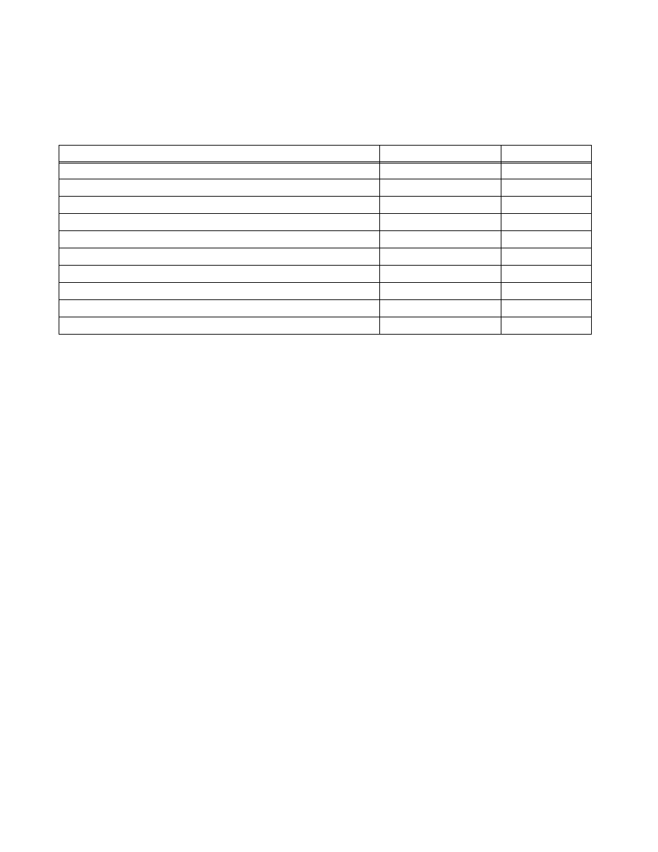
TABLE 1. MATERIAL REQUIRED
MATERIAL
LOCATION
QUANTITY
• PROM U9: Replaces U9 in Distribution Board A6.
Provided in this Kit
1
• PROM U2: Replaces U2 in Digital Board A1.
Provided in this Kit
1
• PROM U24: Replaces U24 in Digital Board A1.
Provided in this Kit
1
• Resistor (Kepco P/N 115-2490) Replaces R82 in Digital Board A1.
Provided in this Kit
1
• Resistor (Kepco P/N 115-2386) Replaces R92 and R93 in Digital Board A1.
Provided in this Kit
2
• Instruction Manual (Kepco P/N 228-1644)
Provided in this Kit
1
• ESD (Electrostatic Discharge) wrist strap (Kepco P/N 114-0080)
Provided in this Kit
1
• IC Extractor (Kepco P/N 114-0079)
Provided in this Kit
1
• Connector (Kepco P/N 142-0527) Mates with Trigger Port.
Provided in this Kit
1
• Capacitor Assembly: Kepco P/N 117-0999 wired to lug (for BOP 36-28MG only)
Provided in this kit