Table 2. high and low alarm adjustment settings, Low alarm (undervoltage) adjustment – KEPCO KDA 24V Alarm Module User Manual
Page 6
6
228-1694 REV 4
062411
KEPCO, INC. 131-38 SANFORD AVENUE FLUSHING, NY. 11355 U.S.A. TEL (718) 461-7000 FAX (718) 767-1102
http://www.kepcopower.com email: [email protected]
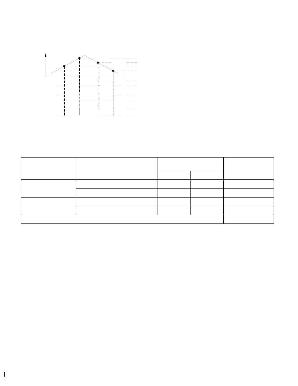
FIGURE 5. DEFAULT SETTINGS FOR HIGH/LOW ALARMS SHOWING HYSTERESIS EFFECTS
Low Alarm (Undervoltage) Adjustment. If the
factory adjusted values are not acceptable, proceed as
follows to adjust the low alarm pick-up and drop-off volt-
ages (V2 and V1 of Figure 5). See Table 2 for the adjust-
ment range
Note: Once all LOW and HIGH alarm adjustments are
acceptable, refer to “Securing Alarm Adjustments”
on page 7 to secure the adjustments
1. Connect a variable output power supply (with a range
exceeding the minimum and maximum values listed in
Table 2) to the channel input as described in the para-
graph titled “Input Connections.” on page 5. Toggle
voltage points may be monitored using the visual indi-
cators (yellow UV, green DC OK and red OV lights) or
monitoring the relay contacts.
2. Turn the LOW trimpot fully CW, then adjust the power
supply to the desired LOW threshold voltage (UVP, V2
shown in Figure 5). If necessary, use a DVM to moni-
tor the power supply voltage.
3. Observe that the UV (yellow) light is lit; no other lights
are lit (relay is deenergized). Slowly (approximately
one complete turn in five seconds) turn the LOW trim
pot CCW until the toggle point (yellow UV LED goes
out, green DC OK goes on, and the relay energizes).
This is V2 - UVP (undervoltage pick-up voltage) as
indicated in Figure 5 and Table 2.
4. To verify the settings lower the voltage of the variable
power supply by about 1.2V. Observe that the yellow
UV light is lit; no other lights are lit (relay is deener-
gized).
5. Then slowly increase the voltage until the toggle point
occurs (yellow UV LED goes out, green DC OK light
goes on, and the relay energizes).
V2
UVP
V4
OVP
V3
OVD
V1
UVD
DC OK LIGHT OFF, RELAY DE-ENERGIZED (FAULT-COM CLOSED)
UV LIGHT ON
UV LIGHT OFF
OV LIGHT ON
OV LIGHT OFF
OVERVOLTAGE
HYSTERESIS
UNDERVOLTAGE
HYSTERESIS
V2 - UVP (UNDERVOLTAGE PICK-UP)
V4 - OVP (OVERVOLTAGE PICK-UP)
V3 - OVD (OVERVOLTAGE DROP-OUT)
V1 - UVD (UNDERVOLTAGE DROP-OUT)
}
}
VOLTAGE
3043498
DC OK LIGHT ON, RELAY ENERGIZED (OK-COM CLOSED)
TABLE 2. HIGH AND LOW ALARM ADJUSTMENT SETTINGS
VOLTAGE
CONDITION
(ADJUSTMENT POT)
SETTING
GUARANTEED ADJUSTMENT
RANGE
FACTORY DEFAULT
VALUES
(±2%)
MIN
MAX
UNDERVOLTAGE
(LOW)
V2: UVP (UNDERVOLTAGE PICK-UP)
16.9V *
21.8V *
19.0V
V1: UVD (UNDERVOLTAGE DROP-OUT)
16.5V *
21.2V *
18.4V
OVERVOLTAGE
(HIGH)
V4: OVP (OVERVOLTAGE PICK-UP)
27.3V *
31.8V *
30.2V
V3: OVD (OVERVOLTAGE DROP-OUT)
26.5V *
31.0V *
29.4V
* Contact factory for alarm settings outside tested max./min. range.