Figure 1. kda 24 series component locations, Kda 24r kda 24a – KEPCO KDA 24V Alarm Module User Manual
Page 2
2
228-1694 REV 4
062411
KEPCO, INC. 131-38 SANFORD AVENUE FLUSHING, NY. 11355 U.S.A. TEL (718) 461-7000 FAX (718) 767-1102
http://www.kepcopower.com email: [email protected]
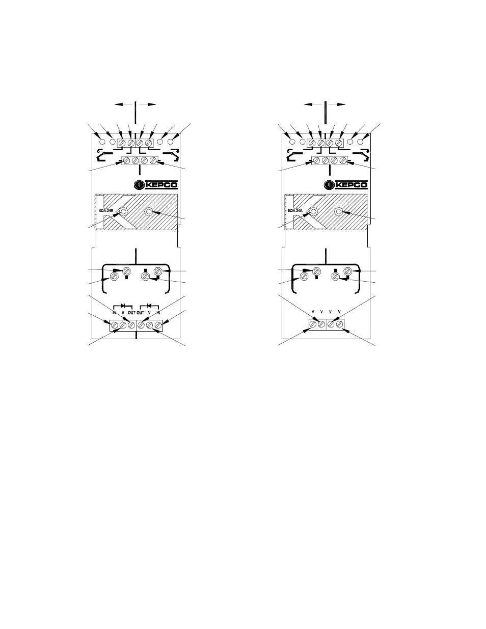
FIGURE 1. KDA 24 SERIES COMPONENT LOCATIONS
+
-
-
+
B
A
VOLTAGE LIMIT ADJ.
HIGH
HIGH
LOW
LOW
A B
A
B
DC OK
COM
OK
COM
FAIL
A
OV
UV
UV
OV
B
OK
FAIL
3043505
LEGEND:
3
4
1
2
5
6
8
7
9
11
10
Note: Channels A and B are Identical.
CHANNEL B
CHANNEL A
5
8
6
7
9
11
4
3
2
1
11
9
8
7
6
5
4
3
2
1
IN+ Terminal (KDA 24R only)
Wire routed from bottom; see appropriate connection
diagram.
V- Terminal
Wire routed from bottom; see appropriate connection
diagram.
OUT+ Terminal (KDA 24R only)
V+ Terminal (KDA 24A only)
Wire routed from bottom; see appropriate connection
diagram.
LOW trimpot
Adjusts undervoltage (UV) setpoint.
HIGH trimpot
Adjusts overvoltage (OV) setpoint.
DC OK Indicator
Lights green when input voltage is within HIGH and
LOW settings.
Light goes off if alarm detected.
FAIL Terminal (Alarm Relay N.C contact)
Relay deenergizes for alarm; provides
connection from COM to FAIL. Wire routed from
top.
OK Terminal (Alarm Relay N.O contact)
Relay normally energized when input power OK;
provides connection from COM to OK. Wire
routed from top.
COM Terminal (Alarm Relay Common)
Wire routed from top.
OV Indicator
Lights red when input voltage is above HIGH
setting.
UV Indicator
Lights yellow when input voltage is below LOW
setting.
1
2
3
4
5
6
7
8
9
11
1
2
3
4
11
7
6
9
8
5
10
10
FAIL
OK
B
OV
UV
UV
OV
A
FAIL
COM
OK
COM
OK
DC
B
A
B
A
LOW
LOW
HIGH
HIGH
VOLTAGE LIMIT ADJ.
+
+
-
+
-
+
B
A
KDA 24R
KDA 24A
CHANNEL B
Note: Channels A and B are Identical.
CHANNEL A