Table 4. dip switch 1 and 2 functions, Figure 4. dip switch configuration, Dip switch configuration – KEPCO HSF 600W Series (suffix A and AM) Operator Manuals User Manual
Page 9: Dip switch 1 and 2 functions
HSF(A) 600W 101013
7
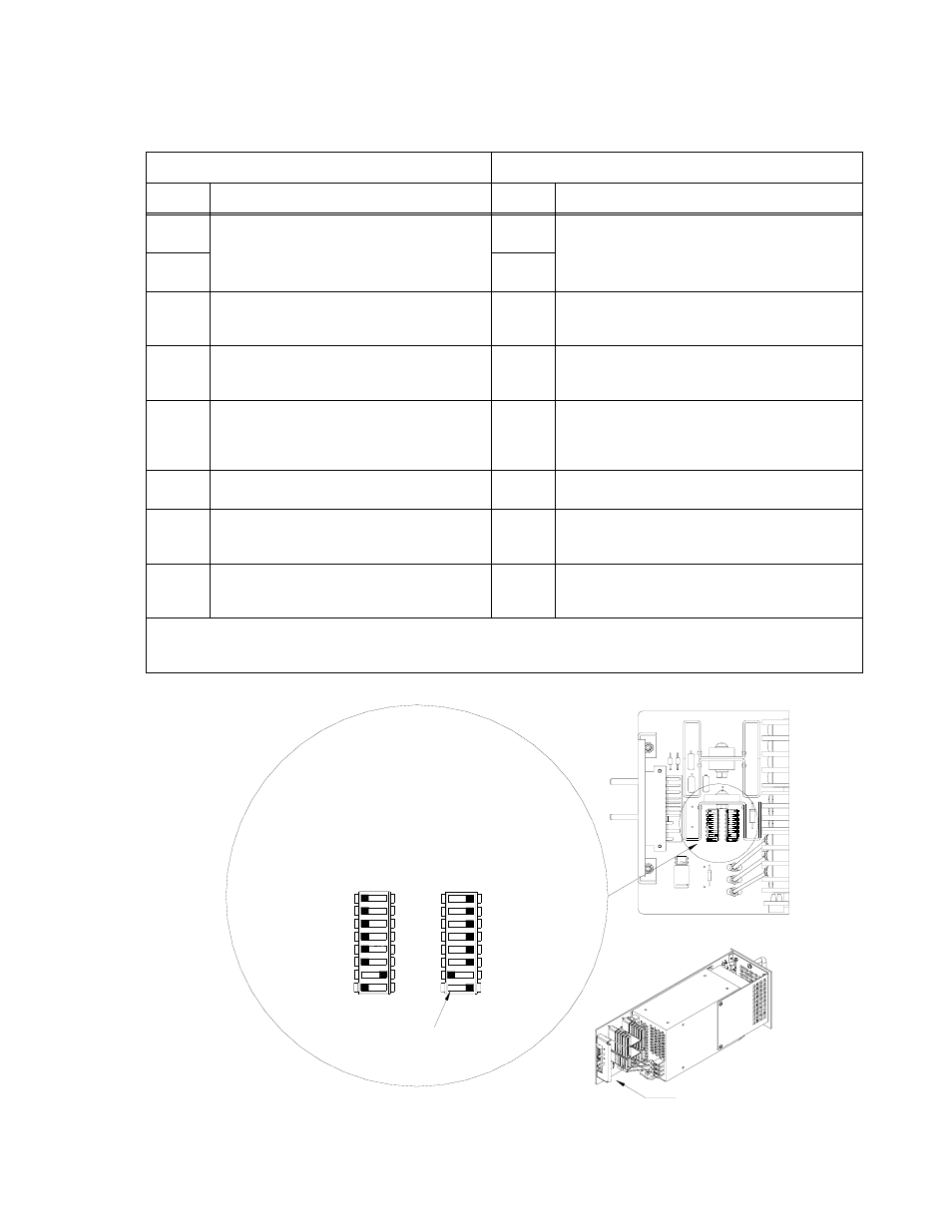
FIGURE 4. DIP SWITCH CONFIGURATION
TABLE 4. DIP SWITCH 1 AND 2 FUNCTIONS
DIP Switch 2 (left)
DIP Switch 1 (right)
Position
Function
Position
Function
1
REF
OFF: Front panel Vadj controls output.
See PAR. 3.4.1.
ON: Remote voltage or resistance controls out-
put. See PAR. 3.4.2.
1
REF
OFF: Remote voltage or resistance controls output.
See PAR. 3.4.2.
ON: Front panel Vadj controls output.
See PAR. 3.4.1.
2
RV
2
RV
3
+RC
OFF: Allows use of front panel RESET button.
ON: Allows use of remote on/off.
See PAR. 3.5.
3
+RC
OFF: Allows use of remote on/off.
ON: Allows use of front panel RESET button.
See PAR. 3.5.
4
-RC
& -PF
OFF: Allows use of front panel RESET button.
ON: Allows use of remote on/off.
See PAR. 3.5.
4
-RC
& -PF
OFF: -PF and -RC isolated from PF/RC Common.
ON: -PF and -RC connected to PF/RC Common.
See PAR. 3.7.2.2.
5
+PF
OFF: Alarm signal from internal isolated relay
contacts. See PAR. 3.7.2.1.
ON: Enables optically-coupled logic alarm. See
PAR. 3.7.2.2.
5
+PF
OFF: Enables optically-coupled logic alarm.
See PAR. 3.7.2.2.
ON: Alarm signal from internal isolated relay con-
tacts. See PAR. 3.7.2.1.
6
CSB
(1)
OFF: Enables Current Share (always off).
ON: N/A
6
CSB
(1)
OFF: N/A
ON: Enables Current Share (always on).
7
-COM
to -S
OFF: Isolates -COM from -S.
ON: Connects -COM to -S.
7
VADJ
to 0
OFF: Vadj adjusts output per Table 2.
ON: Vadj adjusts output to zero.
See Par. 3.4.1.
8
PVB
(2)
Disable
OFF: Enables current sharing (always off)
ON: N/A
8
Alarm
LED
OFF: VDC ON/ALARM stays off for parallel condition.
ON: VDC ON/ALARM glows red for alarm condition.
See Par. 3.7.1
NOTE: BOLD settings indicate factory defaults.
(1) CSB (Current Share Bus bypass) must be in factory default position to enable current sharing.
(2) PVB (Programming Voltage bypass) must be in factory default position to enable current sharing.
OFF
ON
OFF
ON
ALARM LED ENABLE
VADJ TO ZERO
CSB (Always set to ON)
+PF
-RC AND -PF
+RC
RV
REF
3043768
8
8
8
SW1
SW2
4
6
7
5
2
3
1
4
4
5
6
7
6
7
5
1
2
3
2
3
1
CSB DISABLE
8
-RC AND -PF
4
+PF
-COM TO -S
(Always set to OFF) CSB
6
7
5
REF
+RC
RV
2
3
1
NOTE: NOT ALL COMPONENTS SHOWN.
DETAIL VIEW
SW1
SW2
SEE DETAIL VIEW
TAB
(Always set to OFF)
FACTORY DEFAULT SETTINGS:
- Front Panel V
ADJ
control of output
- V
ADJ
Adjust to zero disabled
- Relay Alarm selected
- Visual (red) ALARM indicator enabled
- Front Panel RESET button enabled
- Remote ON-OFF disabled
- Current Share enabled
- (-PF) and (-RC) connected to (-OUT)
- (-COM) connected to (-S)