2 remote voltage control, Dip switch settings for control of output voltage, R. 3.4.2) – KEPCO HSF 600W Series (suffix A and AM) Operator Manuals User Manual
Page 12: R. 3.4.2, Ar. 3.4.2), 6a (factory d
10
HSF(A) 600W 101013
3.4.2 REMOTE VOLTAGE CONTROL
Output voltage can be controlled remotely by means of an external voltage or resistance instead
of by Vadj. Configure the DIP switches as follows:
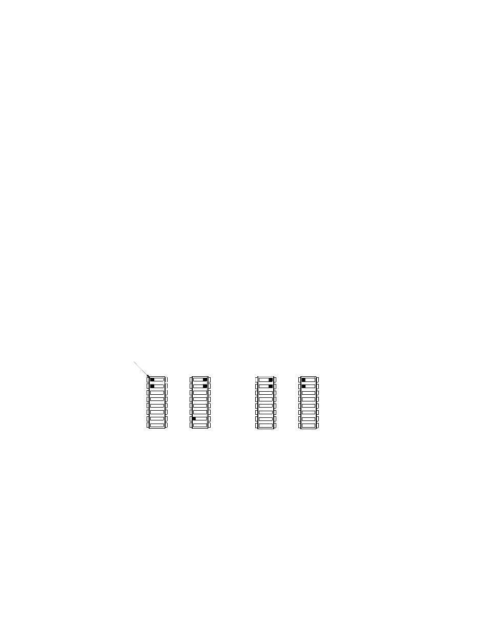
SW1: pos1 to ON, pos2 to ON; SW2: pos 1 to OFF, Pos2 to OFF
NOTE: Configuring the unit for remote output voltage control disables the front panel Vadj con-
trol. To restore Vadj control, configure the DIP switches per PAR. 3.4.1.
When DIP switch positions 1 and 2 are configured as noted above, output voltage can be adjusted
by either an external trimmer pot (resistance) or by an external variable voltage source as shown
in Figure 7. At the rack adapter I/O connector use a shielded wire 6.6 feet (2M) maximum in
length, for connection of pin 2 (REF, Reference), pin 12 (RV, Remote Voltage), and pin 10 (–COM,
Common) of the rack adapter I/O connector to the trimmer control or external voltage source.
Using External Voltage to Control the Output. Connect the external voltage source across the
RV and –COM pins as shown in Figure 7B. By adjusting an external 0 to 6V voltage source (0 to
5.5V for the 48V model), the HSF (A, AM) output voltage can be adjusted within the range specified
in Table 2. To ensure proper operation of the alarm relay, meter (AM Models only) and VDC ON/
ALARM indicator, do not adjust the external voltage below minimum listed in Table 5.
Using External Resistance to Control the Output. Connect the unit to the RV, –COM and REF
pins as shown in Figure 7A. Suggested value for the trimmer control is 20K ohms. Referring to
Figure 7A, Resistor R is used to obtain minimum output voltage required to ensure proper opera-
tion of the alarm relay, meter (AM Models only) and VDC ON/ALARM indicator; see Table 5 for
values.
NOTE: Output voltage may not adjust to 0V due to residual trimmer resistance.
NOTE: If remote output control is not implemented, the factory default for positions 1, 2 and 7
of DIP switches SW1 and SW2 must be restored (Figure 6A).
FIGURE 6. DIP SWITCH SETTINGS FOR CONTROL OF OUTPUT VOLTAGE
NOTE: It is possible that overvoltage protection may be triggered if the output voltage is
decreased to a low level very quickly when the power supply is at a low load condition.
OFF
SW1
3043769
REF 1
RV 2
SW2
1
ON
2
1
2
OFF
1 REF
2 RV
ON
SW1
SW2
1
2
OFF
ON
1
2
OFF
ON
USING Vadj CONTROL
FRONT PANEL VOLTAGE CONTROL
A
B
(FACTORY DEFAULT)
REMOTE VOLTAGE CONTROL
OR VOLTAGE SOURCE
USING EXTERNAL TRIMPOT
REF 1
RV 2
2 RV
1 REF
TAB
7
7 VADJ
TO ZERO
NOTE: SWITCH POSITIONS NOT SHOWN HAVE NO EFFECT ON DESCRIBED FUNCTION.