Figure 4. dip switch configuration, 2 front panel access, Dip switch configuration – KEPCO HSF 600W Series (suffix M and MZ) Operator Manuals User Manual
Page 9: 4), which mu, M models mz models, Detail view
HSF (M) 600W 022713
7
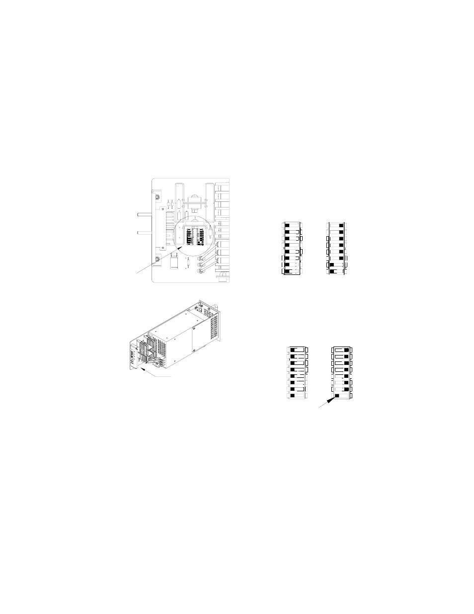
• Positions 5 and 6 of SW1 and SW2 allows alarm signals to be produced from either
internal relay, Form C contacts (one NO, one NC) or open-collector logical alarm signals
(see PAR. 3.8.2).
• MZ Models only: Position 7 of SW1 either enables (default) or disables using the inter-
nal power supply reference voltage to power the DC ON/ALARM indicator. Position 8 of
SW2 either disables (default) or enables using the HSF output voltage to power the DC
ON indicator (see PAR. 3.4.3). Only one of these two must be enabled, the other dis-
abled.
• Position 8 of SW1 either disables (default) or enables the visual alarm indication (see
PAR. 3.8.1).
FIGURE 4. DIP SWITCH CONFIGURATION
3.2
FRONT PANEL ACCESS.
The front panel provides a power ON/OFF switch controlling input power and a "VDC ON" indica-
tor which lights green when the unit is operating. If the unit is connected in a parallel configuration,
the indicator lights red if the unit shuts off automatically, or the POWER switch is set to OFF.
CAUTION: DO NOT repeatedly toggle the power ON/OFF switch as this may cause unit to
fault.
NOTE: The ON/OFF switch must be set to OFF before removing unit from rack adapter.
If remote on-off is not enabled (see PAR. 3.5), the OUTPUT RESET button restores output power
in the event that overcurrent or overvoltage protection has tripped, or thermal overload or fan mal-
function has occurred.
ALARM LED DISABLE
DC ON PWR BY REF
-PF
+PF
-RC
+RC
RV
REF
3043280
DC ON PWR BY OUTP V
-RC
+PF
-COM
-PF
REF
+RC
RV
FACTORY DEFAULT SETTING:
- FRONT PANEL VADJ CONTROL
- RELAY ALARM SELECTED
- VISUAL ALARM DISABLED
- REMOTE ON-OFF DISABLED
- DC ON PWR BY REF V ENABLED
NOTE: NOT ALL COMPONENTS SHOWN.
DETAIL VIEW
SW1
SW2
SEE DETAIL VIEW
FACTORY DEFAULT SETTING:
- FRONT PANEL VADJ CONTROL
- RELAY ALARM SELECTED
- VISUAL ALARM DISABLED
- REMOTE ON-OFF DISABLED
ALARM LED DISABLE
REF
+PF
-COM
N/A
-PF
+RC
-RC
RV
REF
+PF
-PF
-NOT USED
RV
+RC
-RC
M MODELS
MZ MODELS
SEE APPLICABLE
DESCRIPTION
FOR M OR MZ
MODELS.
ON
5
6
8
7
SW2
OFF
2
1
4
3
5
5
5
TAB
7
8
6
SW1
8
6
7
7
8
6
ON
OFF
4
3
2
1
3
4
2
1
4
3
2
1
4
4
8
7
5
6
8
8
8
6
7
7
5
5
6
6
7
5
4
3
2
1
OFF
3
4
3
2
1
2
1
3
1
2
OFF
ON
ON