1 dip switch configuration, R. 3.1), Airflow – KEPCO HSF 600W Series (suffix M and MZ) Operator Manuals User Manual
Page 8
6
HSF (M) 600W 022713
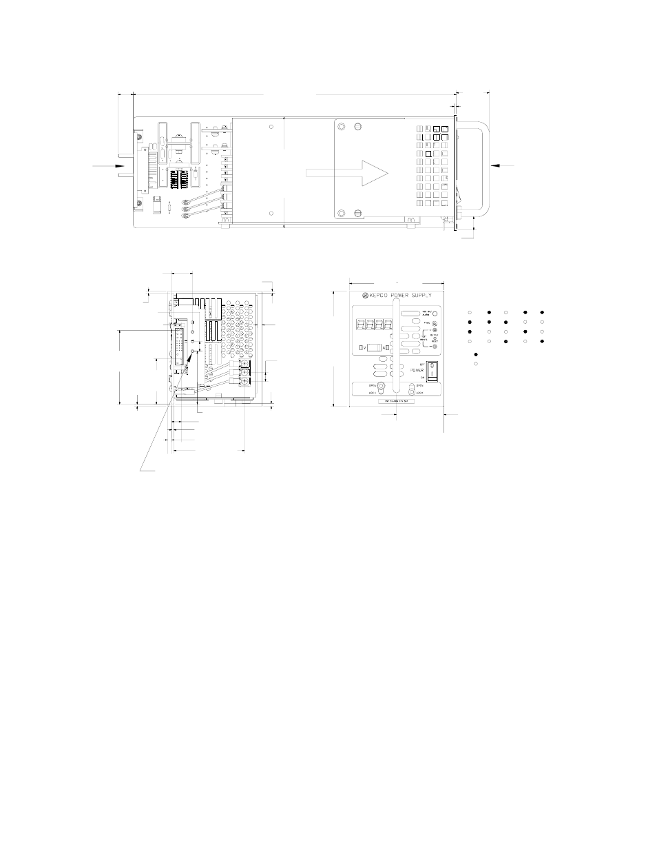
FIGURE 3. MECHANICAL OUTLINE DRAWING, HSF 600W M AND MZ MODELS
3.
FEATURES
3.1
DIP SWITCH CONFIGURATION
The HSF 600W Series M and MZ models incorporate two DIP switches, SW1 and SW2 (see Fig-
ure 4), which must be configured before the unit is installed in the rack adapter. The DIP switches
control the following parameters:
• Positions 1, and 2 of SW1 and SW2 allow the output to be controlled either by the front
panel Vadj control (see PAR. 3.4.1) or by remote control using either an external trimpot
or voltage source (see PAR. 3.4.2). These positions can also be configured to allow a
master/slave combination to be controlled either by the front panel Vadj control or by
remote control using either an external trimpot or voltage source (see PAR 3.4).
• Positions 3 and 4 of SW1 and SW2 either allow the front panel reset button to be used to
reset the unit after a fault or allow Remote on-off via mechanical switch or logic level
(see PAR. 3.5).
1.500
[38.1]
0.093 [2.4]
14.667 [372.5]
5
.0
4
0
[1
2
8.
0]
0.188 [4.8]
0.093 [2.4]
0.093
[2.4]
0.127
[3.2]
0.430 [10.9]
2.065
[52.5]
3.353
[85.2]
0.337 [8.5]
0.085 [2.2]
0.204 [5.2]
0.090 [2.3]
0.943 [23.9]
2.408 [61.2]
0.438 [11.1]
0.394
[10.0]
3.216 [81.7]
0.606 [15.4]
0.690 [17.5]
FRONT VIEW
REAR VIEW
SEE
REAR
VIEW
SEE
FRONT
VIEW
NOTES:
1. MATERIAL:
A) BACKPLATE 0.064" THK. ALUM. 5052-H32
B) PCB 0.063" THK FR-4
C) FRONT PANEL 0.090 THK. ALUM. 6061-T6
2. FINISH:
FRONT PANEL -KEPCO DUAL TONE GRAY
3. MODULE IS KEYED AS SHOWN IN DETAIL
4. DIMENSIONS ARE IN INCHES, [DIMENSIONS IN BRACKETS
ARE IN MILLIMETERS].
3043128
15V
12V
= PIN PRESENT
= PIN MISSING
KEYING
DETAIL "A"
SEE DETAIL "A"
24V 28V 48V
5
.2
1
8
[
1
32
.5
]
4.288 [108.9]
2.144
[54.46]
AIRFLOW