Table 3. power supply ratings and specifications, Power supply ratings and specifications, Able 3 co – KEPCO HSF 300W Series (no suffix, suffix M and MZ) Operator Manuals User Manual
Page 6
4
HSF (M) 300W 030413
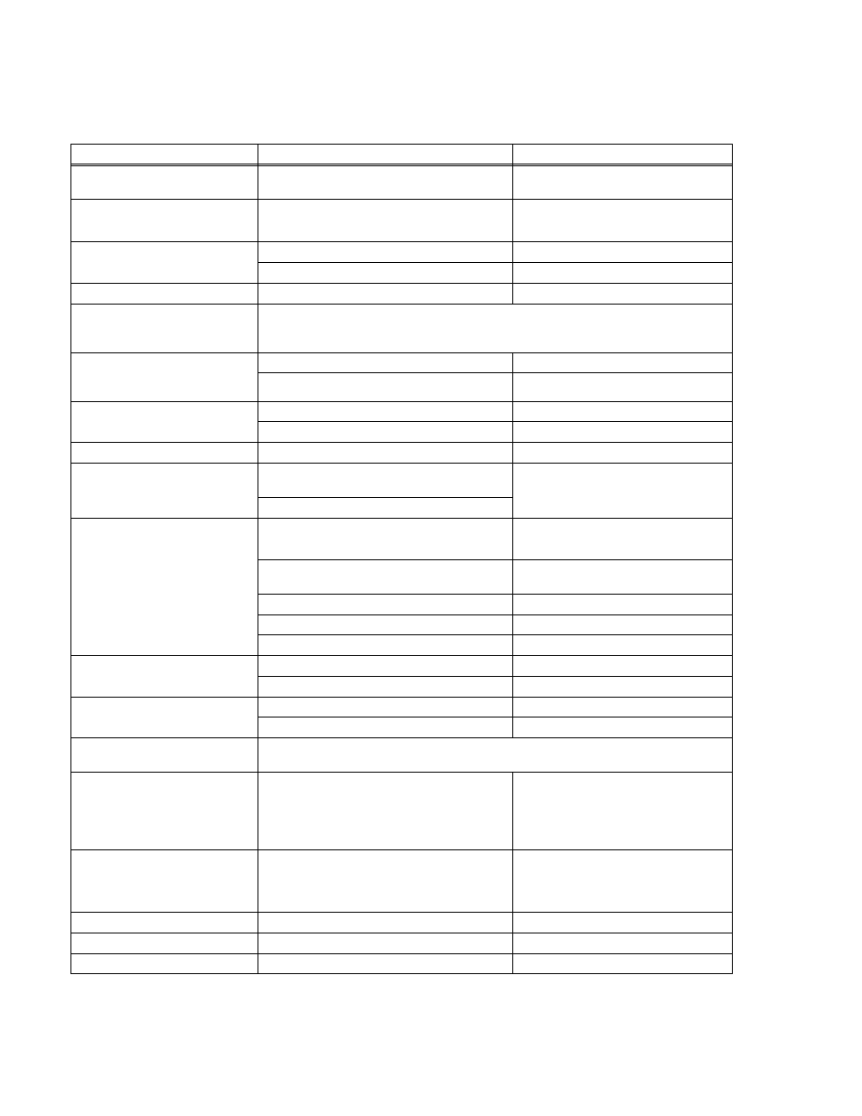
TABLE 3. POWER SUPPLY RATINGS AND SPECIFICATIONS
CHARACTERISTIC
SPECIFICATION
CONDITION/NOTES
Input Voltage
Nominal: 100-120V a-c, 200-240V a-c
Range: 85-265V a-c, 110-370V d-c
0 to 100% load, -10 to 40°C
Input Source Frequency
Nominal: 50-60 Hz
Range: 47-440 Hz
0 to 100% load, -10 to 40°C
At 440 Hz leakage current exceeds
UL/VDE safety spec. limit.
Input Current: (Maximum Load At
25°C with Nominal Output Voltage)
4.4A rms max.
100 - 120V a-c
2.2A rms max.
200 - 240V a-c
Switching Frequency
140KHz typ.
Forward Converter
Input Protection
A limiting resistor in series with a resistor fuse (and thyristor circuit) reduces start-up surge.
The internal power supply is protected against shorts by an input fuse. Fuse value 10.0A at
250 Volts
Input Surge cold start, interval > 30
sec ( First surge only, not including
current flow into EMI filter)
15A typ., 20A max. first surge
100 - 120V ac
30A typ., 40 max. first surge
200- 240 V ac
Leakage Current:
0.24mA typ., 0.3mA max.
120V a-c, 60Hz per IEC 950 and UL1950
0.31mA typ., 0.38mA max.
240V a-c, 60Hz per IEC 950 and UL1950
Power Factor
0.99 typical
Rated output, rated input
Transient Recovery
excursion
characteristic
±4% maximum
50% to 100% load,
transient time >50
µ
sec
recovery time 1 ms maximum
Stabilization
Source Effect (min - max) ±0.1% Typical, ±0.2% Maximum
85 to 132V a-c, 170 to 265V a-c
Load Effect ±0.3% Typical, ±2% Maximum (default)
±0.3% Typical, ±0.6% Maximum (see PAR. 3.4)
Individual Mode: 0%-100% load change
Current Sharing: 10%-100% load change
Temperature Effect ±0.5% Typical, ±1.0% Maximum
–10° to 40°C
Combined Effect ±0.9% Typical, ±1.8% Maximum
Source, Load and Temperature
Time Effect 0.2% Typical, 0.5% Maximum
1/2 to 8 hours at 25°C
Start-up Time
280 msec Typical, 350 msec Maximum
100V a-c
150 msec Typical, 210 msec Maximum
240V a-c
Output Hold-up Time
30 msec Typical, 20 msec Minimum.
100V a-c
40 msec Typical, 20 msec Minimum.
240V a-c
Overvoltage Protection
When the Power Supply goes into an overvoltage condition, the output is cut OFF. See PAR.
3.7.1.
Remote Control ON/OFF:
±RC pins control on/off as follows:
“High”, 2.4V to 24V (or open), unit OFF- Fan Off;
“Low”, 0.0V to 0.4V (or closed), unit ON.
Source current: 1.6mA maximum at low level
Sink current: 1.0 mA maximum at high level.
Must be enabled by DIP switch positions 3
and 4 (see PAR. 3.4.3).
Meter (displays voltage or current;
front panel switch-selectable)
Voltmeter Accuracy: ±3%
Ammeter Accuracy: ±5% for loads between 10%-
100%
Voltmeter reads sense lines; use remote
sensing to display voltage at load.
Ammeter accuracy degrades significantly
for loads less than 10%
Operating Temperature:
-10 to 40°C
(see Figure 2.)
Startup Temperature
-10 to -20°C
(see Figure 2.)
Storage Temperature:
-30°C to +75°C