Figure 7. connections for remote voltage control, 3 vdc on/alarm indicator power options, 5 remote on-off – KEPCO HSF 300W Series (no suffix, suffix M and MZ) Operator Manuals User Manual
Page 12: Connections for remote voltage control, Dip switch settings for vdc on/alarm power options, R. 3.4.3), R 3.4.3), r, Able 5 for, R. 3.4.3), the output, E 7. at the ra
10
HSF (M) 300W 030413
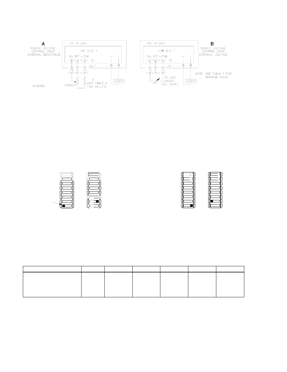
FIGURE 7. CONNECTIONS FOR REMOTE VOLTAGE CONTROL
3.4.3 VDC ON/ALARM INDICATOR POWER OPTIONS
To use the internal power supply reference voltage to power the VDC ON/ALARM indicator, set
Position 7 of SW1 to ON and Position 8 of SW2 to OFF (default) (see Figure 8A). Load effect is
±1% maximum. To use the HSF output voltage to power the VDC ON/ALARM indicator, set Posi-
tion 7 of SW1 to OFF and Position 8 of SW2 to ON (see Figure 8B). Load effect is ±0.6% maxi-
mum, however the minimums specified in Table 5 must be observed for the indicator to function.
FIGURE 8. DIP SWITCH SETTINGS FOR VDC ON/ALARM POWER OPTIONS
Table 5 lists the minimum HSF output voltage required to maintain VDC ON indicator function for
this case. Maximum output voltage of unit might cause overvoltage trip if SW2, position 8 is
enabled. If this occurs, turn Vadj trim pot counterclockwise to reduce output voltage, then reset the
unit.
3.5
REMOTE ON-OFF
When power is ON at the source, the output may be turned ON or OFF using the ±RC signals if
the remote ON-OFF feature is enabled. Note that when remote ON-OFF is enabled, the RESET
OUTPUT switch does not function. Remote ON-OFF is enabled by setting DIP switch positions 3
and 4 as shown in Figure 9B. The +RC and –RC signals (at the rack adapter I/O connector, pins
15 and 8, respectively) then turn the unit on or off. These pins accept a logic level (2.4V to 24V
TABLE 5. CONDITIONS FOR VDC ON/ALARM LED OPERATION POWERED BY
OUTPUT
MODEL
HSF 5-60M
HSF 12-53MZ
HSF 15-43MZ
HSF 24-27MZ
HSF 28-23MZ
HSF 48-13MZ
Minimum HSF output voltage
required for VDC ON LED to
function when SW 2 position 8 is
ON and SW 1 position 7 is OFF
(Volts d-c).
3.3
3.3
3.5
4.5
5
8
3043492
7
7 DC ON PWR BY REF
7
SW1
8
SW2
8
OFF
ON
OFF
ON
USE REFERENCE SUPPLY
(FACTORY DEFAULT)
TO POWER "DC ON"
A
TO POWER "DC ON"
USE HSF OUTPUT VOLTAGE
B
(REQUIRES MINIMUM OUTPUT VOLTAGE)
7
8
8
SW1
7
SW2
OFF
ON
ON
OFF
DC ON PWR BY OUTPUT V 8
8
7
7
8
8
7
TAB