Table 2. output ratings and specifications, Figure 2. power rating vs. temperature, Power rating vs. temperature – KEPCO HSF 300W Series (no suffix, suffix M and MZ) Operator Manuals User Manual
Page 5: Output ratings and specifications, Able 2 cont
HSF (M) 300W 030413
3
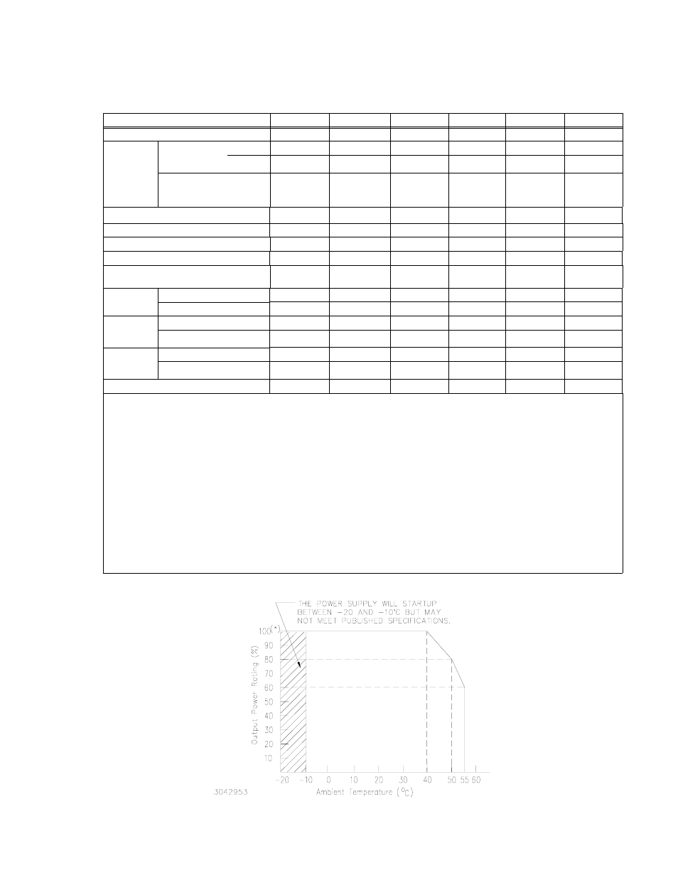
FIGURE 2. POWER RATING VS. TEMPERATURE
TABLE 2. OUTPUT RATINGS AND SPECIFICATIONS
HSF MODEL
5-60*
12-27*
15-22*
24-14*
28-12*
48-7*
Output Volts d-c (nominal)
5
12
15
24
28
48
Output
Adjustment
Range
(1)(2)
Using front
panel trimpot
(Volts d-c)
(3)
M
0 to 5.5
5.5 to 13.8
(8)
7 to 17.4
(8)
7 to 28.2
(8)
7 to 33
(8)
7 to 52.2
(8)
MZ
(3)
0 to 5.5
0 to 13.8
0 to 17.4
0 to 28.2
0 to 33
0 to 52.2
Using Voltage source or
external 5K ohm trimpot
(3)
(Volts d-c)
0 to 5.5
0 to 13.8
0 to 17.4
0 to 28.2
0 to 33
0 to 52.2
Output Current (nominal) (Amps)
60
27
22
14
12
7
Maximum Output Power (Watts)
(4)
300
300
300
300
300
300
Overcurrent Setting (Amps)
(5)
63-78
28.4-35.1
23.1-28.6
14.7-18.2
12.6-15.6
7.4-9.1
Short Circuit Current (Amps)
82
35
29
20
17
11
Overvoltage Protection (OVP)
(Volts d-c)
(6)
5.7 - 7.0
14.3 - 16.8
18.0 - 24.0
29.3 - 33.6
34.2 - 39.2
54.5 - 59.8
Efficiency
(% typ.)
AC Input 100V
72
74
75
78
78
79
AC Input 200V
78
78
79
82
82
83
Power Fac-
tor
(typ.)
AC Input 100V
0.99
0.99
0.99
0.99
0.99
0.99
AC Input 200V
0.95
0.95
0.95
0.95
0.95
0.95
Ripple &
Noise
(7)
(mV, p-p)
ripple 80
120
120
150
150
200
ripple noise
120
150
150
200
200
200
Sense Resistor (IMON) values (Ohms)
0.002
0.01
0.01
0.02
0.05
0.02
*
Unless otherwise noted, specifications apply to both M and MZ models.
(1)
M Models only: To adjust output voltage down to approximately 0V use external voltage source or resistance (see PAR.
3.4.2). Refer to Table 4 for minimum conditions required to maintain proper operation of alarm relay, meter and visual LED
indicator.
(2)
If the visual LED indicator is powered from the HSF output (see PAR 3.4.3), refer to Table 5 for minimum conditions required
to maintain functionality of the indicator.
(3)
Using trimpot to attain voltages outside the specified adjustment range may trigger undervoltage (PAR 3.7.4) or overvoltage
(PAR 3.7.1) faults. Recovery is by removing, and after approximately 40 seconds, reapplying AC input power or by reset
(open and close) at ±RC terminals (no delay).
(4)
See Figure 2 for power derating.
(5)
Square type. Output voltage returns automatically only if cause is removed within 30 seconds (see PAR. 3.7.2).
(6)
When overvoltage is detected, output is shut OFF. Recovery is by removing, and after approximately 40 seconds, reapplying
AC input power or by reset (open and close) at ±RC terminals (no delay).
(7)
Ripple and noise levels above are satisfied when conditions are 0 to 100% load, 0 to 40°C (load is derated from 40 to 55°C,
see Figure 2), and bandwidth
≤ 100MHz.
(8)
Range shown is operating range; minimum range upon startup is 0.5V higher than minimum operating range shown.