Dip switch settings for control of output voltage, Able 4 for – KEPCO HSF 300W Series (no suffix, suffix M and MZ) Operator Manuals User Manual
Page 11
HSF (M) 300W 030413
9
trimmer pot (resistance) or by an external variable voltage source connected across the rack
adapter I/O connector pin 12 (RV, Remote Voltage) and pin 10 (–COM, Common) as shown in
Figure 7. At the rack adapter I/O connector use a shielded wire 6.6 feet (2M) maximum in length,
for connection of REF (pin 2), RV (pin 12), and –COM (pin 10) to the trimmer control or external
voltage source.
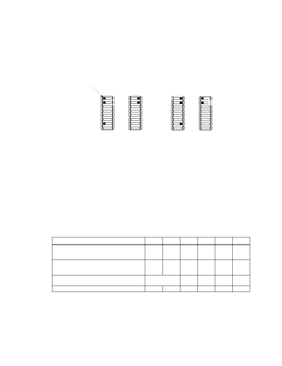
NOTE:If remote voltage control is not implemented, the factory default for positions 1, 2 and 7 of DIP
switches SW1 and SW2 must be restored (Figure 6A).
FIGURE 6. DIP SWITCH SETTINGS FOR CONTROL OF OUTPUT VOLTAGE
It is possible that overvoltage protection may be triggered if the output voltage is decreased to a low
level very quickly when the power supply is at a low load condition.
RESISTANCE: Connect the external trimmer as shown in Figure 7A. Suggested value for the trim-
mer control is 5K ohms. For M Models only: Resistor R (see Figure 7A) is used to obtain mini-
mum output voltage required to ensure proper operation of the alarm relay and LED indicator; see
Table 4 for values. NOTE: Output voltage may not adjust to 0V due to residual trimmer resistance.
VOLTAGE. By adjusting an external 0 to 6V voltage source (0 to 5.5V for the 48V model), the HSF
power supply output voltage can be adjusted as specified in Table 2.
For M Models (except HSF 5-60M) only: To ensure proper operation of the alarm relay, meter
and LED indicators, do not adjust external voltage below minimum listed in Table 4. Connect the
voltage source across the RV and –COM pins as shown in Figure 7B.
For MZ Models and HSF 5-60M only: The meter and relay are powered internally and are not
dependent on HSF output to maintain function.
TABLE 4. MINIMUM CONDITIONS FOR RELAY, METER AND LED OPERATION
HSF MODEL
5-60M
2
12-27M
15-22M
24-14M
28-12M
48-7M
Minimum HSF output voltage required for continuous
relay, meter and LED functioning (Volts d-c); startup
minimum are 0.5V higher except for HSF 5-60M.
1
No limit
5.5
7
7
7
7
Minimum resistance of Limit resistor R (Figure 7A) in
series with 5K ohm Trimpot to ensure proper operation
of LEDs, meter and relay (Ohms).
1
No limit
2.61K
1.91K
1.3K
1.1K
634
Minimum external voltage (Figure 7B) to ensure proper
operation of LEDs, meter and relay. (Volts d-c).
1
No limit
2.3
2.43
1.43
1.28
0.68
Voltage source range (Volts d-c)
0 - 6
0 - 6
0 - 6
0 - 6
0 - 6
0 - 5.5
1 - If operating below minimums listed, see PAR. 3.8.2.2 to implement ±PF alarm signals to monitor power supply status.
2 - 5V model includes auxiliary supply that powers the relay, meter and LED independent of output voltage.
OFF
SW1
3043279
COM 7
REF 1
RV 2
7
SW2
1
ON
2
1
2
OFF
1 REF
2 RV
ON
SW1
SW2
7
1
2
OFF
ON
1
2
OFF
ON
USING Vadj CONTROL
FRONT PANEL VOLTAGE CONTROL
A
B
(FACTORY DEFAULT)
REMOTE VOLTAGE CONTROL
OR VOLTAGE SOURCE
USING EXTERNAL TRIMPOT
COM 7
REF 1
RV 2
2 RV
1 REF
TAB