Run test, Changing settings, Figure 3. test setup, typical – KEPCO EL Series Quick Start Guide (Firmware Version 4.00 and higher) User Manual
Page 4: Of “changing
4
228-1687 REV 4
071913
KEPCO, INC. " 131-38 SANFORD AVENUE " FLUSHING, NY. 11355 U.S.A. " TEL (718) 461-7000 " FAX (718) 767-1102
http://www.kepcopower.com " email: [email protected]
RUN TEST. To run a test proceed as follows: If the test
is run immediately after unpacking and installing the unit
without changing the factory default settings, the mode
will be CI mode and setpoint at 0 Amperes). To change
the settings before running the test, see CHANGING SET-
TINGS below. Once the settings are changed, the new
settings will be saved when the unit is turned off, and will
be restored when the unit is powered up.
1. Set desired mode (see steps 1 and 2 of “Changing
Settings.” on page 4) and resolution (see “Set Setpoint
Adjustment Resolution.” on page 2).
2. Press the green LOAD button to engage the load. The
LOAD indicator changes from green to amber, indicat-
ing the load is engaged with the source under test.
3. The load will respond according to the default settings
or to your prior memorized settings
4. If the load has not been previously set up, then it will
be in the CI mode and will engage at 0 Amperes
5. Turn the multi-turn CONTROL knob to the desired cur-
rent.
6. At the completion of the test, press LOAD switch to
disengage the load; LOAD indicator changes from
amber to green.
CHANGING SETTINGS. Prior to engaging the load
you may preset the load to a given set of conditions. After
presetting conditions, you may need to fine tune the
actual values depending on your test conditions. (see EL
Operator manual for details.)
1. Depress and hold the CONTROL knob until the Green
LOAD button turns off (~ 3 seconds), indicating you
may rotate the knob and select the desired mode.
2. While holding the knob in, rotate it until the desired
mode is selected as indicated in Table 2, then release
the knob. The mode indicators will illuminate in the
order shown in Table 1.
3. To adjust the value (setpoint) for the selected mode,
rotate the CONTROL knob (without depressing); see
Table 3. To make the adjustment easier adjust resolu-
tion as desired (see “Set Setpoint Adjustment Resolu-
tion.” on page 2).
4. When satisfied with the setting, press the green LOAD
button to begin (engage) the test. The LOAD indicator
changes from green to amber to show the load is
engaged.
5. The selected mode setpoint value may be changed
during the test by rotating the CONTROL knob (see
Table 3).
6. At the completion of the test, press LOAD switch to
disengage the load; LOAD indicator changes from
amber to green.
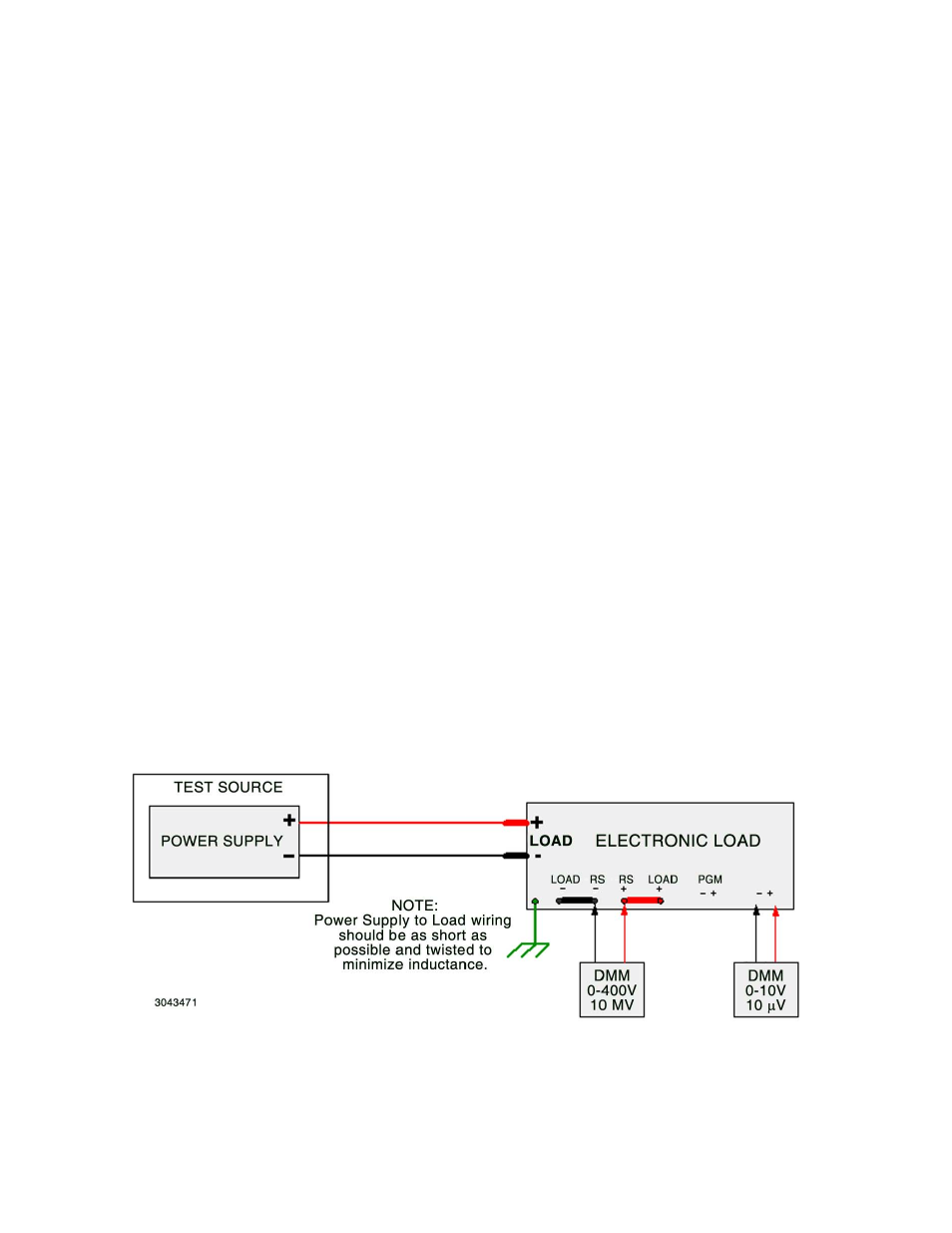
FIGURE 3. TEST SETUP, TYPICAL