Connections, Iv — operation, Controls and indicators – KEPCO EL Series Quick Start Guide (Firmware Version 4.00 and higher) User Manual
Page 2: Startup, Table 1. front panel functions, Set setpoint adjustment resolution
2
228-1687 REV 4
071913
KEPCO, INC. " 131-38 SANFORD AVENUE " FLUSHING, NY. 11355 U.S.A. " TEL (718) 461-7000 " FAX (718) 767-1102
http://www.kepcopower.com " email: [email protected]
CAUTION: Refer to the Operator’s manual for optional
slide installation. Failure to use slide and screws
specified will damage the unit and void the warranty.
CONNECTIONS. See Figure 3 for typical test connec-
tions. The Series EL is capable of drawing very high cur-
rents. Connections between the UUT and the Series EL
must be properly sized to carry the maximum current.
Additionally, it is extremely important to ensure all connec-
tions are tight and corrosion free. See Section II, Safety
Warnings. Use low resistance hardware supplied with the
unit for connections to ± LOAD terminals. Regular inspec-
tion of ±LOAD connection tightness is important.
Connect the Series EL to the UUT using cabling
appropriate for the current expected during testing.
CAUTION: Ensure polarity is correct - reversed
polarity will cause immediate and significant damage
to the Series EL and/or the UUT. Contact Kepco if
assistance is needed in selecting the appropriate wire
size, length and physical configuration. Ensure all
connectors are suitable for the current and voltage
expected and that connections are tight. Connections
should be re-checked to ensure continued low-resistance
connections on a regular basis. CAUTION: When
connecting the Series EL to the UUT be very careful
not to accidentally short the UUT output while
connecting the wiring. Best practice is to make the
connection to the UUT Positive (+) output connector
the last connection.
Refer to the EL Operator manual for connections required
for remote control.
IV — OPERATION
Operation is either from the front panel (local) or via com-
puter control (remote). For remote operation, refer to the
EL Operator manual.
CONTROLS AND INDICATORS. Figure 2 shows the
location of front panel components described in Table 1.
STARTUP.
1. After all connections are completed, turn on system by
setting ON/OFF switch to ON.
2. After warming up for about 15 seconds, the unit begins
the power-up self-test.
3. Set the desired Mode (see steps 1 and 2 of “Changing
4. When ready, the LOAD switch-indicator lights green.
The VOLTS display shows the voltage of the source
under test. AMPS and KW displays indicate zero.
SET SETPOINT ADJUSTMENT RESOLUTION.
1. Momentarily press the CONTROL knob a number of
times to select the digit representing the resolution
needed for adjustment during test (selected digit
blinks).
2. For example, if 1A per click of adjustment is desired,
select the most significant digit (MSD), which yields 1
Amp per click. If finer resolution is desired, select a
less significant digit such as 100mA or 10mA per click
(see Figure 1). NOTE: Leading zeroes are sup-
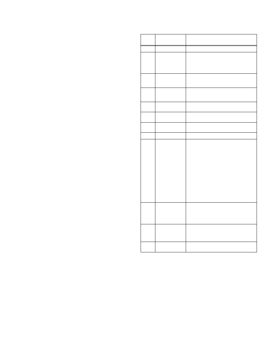
TABLE 1. FRONT PANEL FUNCTIONS
SEE
FIG. 1
COMPONENT
FUNCTION
1
AMPS display
Displays the load test current in Amps
2
CR indicator
On (solid) indicates Constant Resistance
Mode; factory default set to 1000 Ohms. On
(blinking) indicates Constant Conductance
Mode; factory default set to 1mS (0.001
siemens, I/E).
3
CI indicator
On to indicate Constant Current Mode
(factory default setpoint: 0A. After use, the
last used setpoint is retained).
4
CV indicator
On to indicate Constant Voltage Mode
(factory default setpoint: maximum load
voltage).
5
CP indicator
On to indicate Constant Power Mode (factory
default setpoint: 0 kilowatts).
6
Power ON/OFF
switch
Rocker switch: press top half to turn power
on, bottom half to turn power off.
7
LAN indicator
On indicates optional LAN connection is
active.
8
LOCAL indicator
On indicates Local mode is active.
9
CONTROL
rotary control/
pushbutton switch
When LOCAL is active, three functions are
available as follows:
a. Select Mode: Press, hold (at least 3
seconds) and rotate knob to select mode
indicated by the CI, CR, CV and CP
indicators (see Table 2).
b. Set Value: Rotate knob to adjust the level
of the controlled parameter: current, voltage,
resistance, conductance or power (see Table
3). Rotate clockwise to increase,
counterclockwise to decrease. Settings are
stored and will be available at next power-up.
c. Select Digit: Momentarily press knob to
select one digit (blinks). Convenience
function allows adjustment of one digit at a
time.
10
LOAD
pushbutton
switch/indicator
Indicator lights to show load status: green
(ready to operate), amber (load is engaged)
or blinking red (fault condition exists). Press
switch to engage/disengage load or clear
fault indication.
11
KW display
Displays the power (Amps x Volts) being
dissipated by the load in kilowatts. Also
momentarily indicates resistance (in Ohms)
or conductance (in Siemens) setting.
12
VOLTS display
Displays test voltage from UUT applied to the
load in Volts.