2 electrical, Figure 2. ca 400 backplate assembly, 3 mechanical – KEPCO CA 400 User Manual
Page 7: 4 accessories, Electrical, Mechanical, Accessories, Ca 400 backplate assembly
2
CA 400 060700
1.2
ELECTRICAL
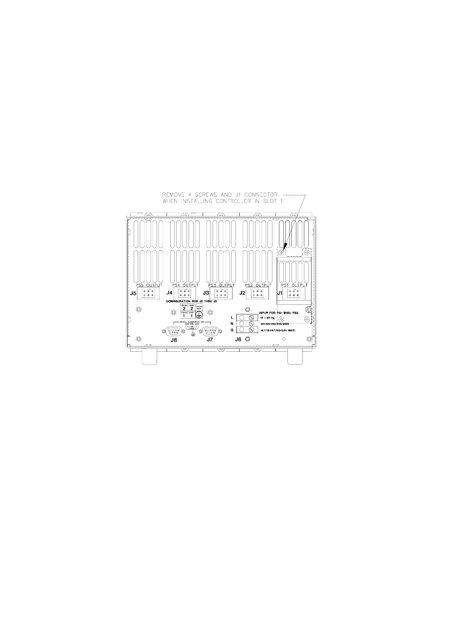
The rack adapter contains a PCB backplane whose connectors mate with the MST Power
Module plug-in connectors to facilitate rapid installation of the power modules. The a-c input
terminal blocks (J6) on the backplate assembly (Figure 2) distributes input power to five PCB-
mounted a-c input/control bus power connectors (P1 - P5) as shown in Figure 4. Two-wire
IEEE 1118 control bus data is supplied to the five a-c input/control bus power supply connec-
tors via two 9-pin connectors (six pins are not used), J7 and J8 on the backplate assembly.
The utilized pins of the two IEEE 1118 control bus connectors are paralleled, facilitating "daisy
chain" control bus configurations. A shield connection is routed to connector P1 for grounding
within the controller when a controller is installed; otherwise this connection is not used.
The d-c output connectors of the MST power supplies installed in the rack adapter are accessed
via connector extenders (J1 - J5) mounted on the backplate assembly.
FIGURE 2. CA 400 BACKPLATE ASSEMBLY
1.3
MECHANICAL
The rack adapter is pre-drilled to accept chassis slides. It is equipped with four metal foot
attachments; mounting ears and rack adapter handles are available as accessories (see Table
1). The rack adapter can use 18-inch (457.2 mm) Jonathon Model 110-QD-18-2 chassis slides.
The rack adapter can be equipped with optional 1/5 rack blank filler panels (Kepco Model RFP
55-1) if the full complement of five power supplies is not utilized.
Mechanical dimensions, material, and finish of the Kepco Model CA 400 Rack Adapter are pro-
vided in Figure 5.
1.4
ACCESSORIES
Table 1 lists the accessories provided with the CA 400 Rack Adapter. A controller and up to 27
MST, MAT or MBT Power Modules can be connected in a daisy chain configuration as shown in
Figure 3. The last power module control bus outlet (in the daisy chain) must be terminated with
an IEEE1118 Control Bus Terminator supplied with the Rack Adapter; even if only one Rack
1448