KANOMAX 6162 Anemomaster User Manual
Page 24
3. Measurement Mode
18
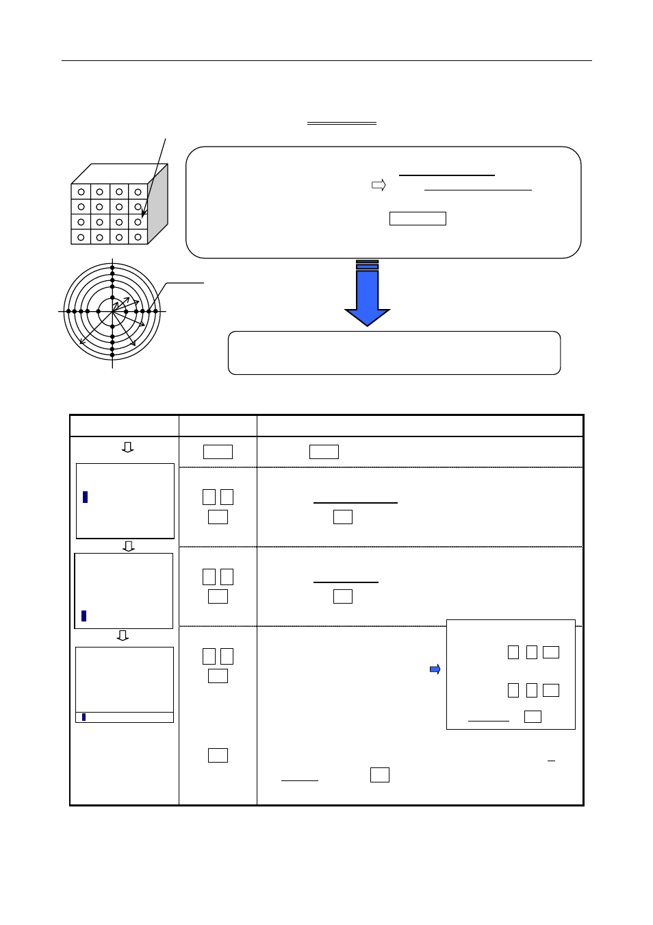
3.3 How to Measure Flow Rate in the Duct [Flow Rate Mode]
Display Key
Procedure
MENU
(1) Press MENU key.
△
, ▽
SET
(2) Select 2. MEASUREMENT.
Then press SET key.
△
, ▽
SET
(3) Select 3. FLOW RATE.
Then press SET key.
△
, ▽
SET
SET
(4) Set the measurement condition
in the same manner as when
configuring Average Mode (P14).
When the measurement condition is configured, select 7.
SET OK!, and press SET key.
Air Volume (F) = Average Air Velocity (U) × Cross Section (AREA)
indicated in m³/hour and m³/min
Example
POINT 1 --- AVE 1 = Σ DATA (N)/N
POINT 2 --- AVE 2 =Σ DATA (N)/N
POINT M --- AVE M =Σ DATA (N)/N
* To start a measurement at each point: START/STOP key
* For detailed information on measuring at each point, refer to 3.2 How to
Collect Data at Certain Time Intervals [Interval Mode] (P16).
Average Air Velocity
U =
(AVE1+AVE2+···AVE N)
No. of Points (M)
Measuring Point
(POINT)
Duct Area
r1=0.316R
r2=0.548R
r3=0.707R
r4=0.837R
r5=0.949R
R
r1 r2 r3
r4
r5
Measuring Point
Calculation result
Measurement
FLOW RATE
(a)
☆
To select the item to be
changed
△
, ▽⇨SET
☆
To change setting value
and YES/NO.
△
, ▽⇨SET
☆
Setting is complete.
7. SET OK! ⇨ SET
< MENU >
1. MONITOR
2
. MEASUREMENT
3. DATA OUTPUT
4. MEMORY CLEAR
5. UTILITY
< MEASUREMENT >
1. AVERAGE
2. INTERVAL
3
. FLOW RATE
< FLOW >
1. S-TIME(S) 01
2. DATA (N) 010
3. POINTS 016
4. AREA(m2) 0.100
5. MEMORY YES
6. PRINT YES
7
. SET OK!
Screen>