GW Instek GRF-3300 Series Teacher Manual User Manual
Page 9
16 Microstrip Line Filters
3
317
16-2-2. Solution
Referring to Table 7-5, since
Z/Zc=1.5 20dB attenuation is 20dB at 3GHz, the
order becomes 7. From Table 7-1, we find the normalized values of g1 to g8 as follows:
x
g1=g7=0.4450
x
g2=g6=1.2470
x
g3=g5=1.8019
x
g4=2.0000
x
g8=1.0000
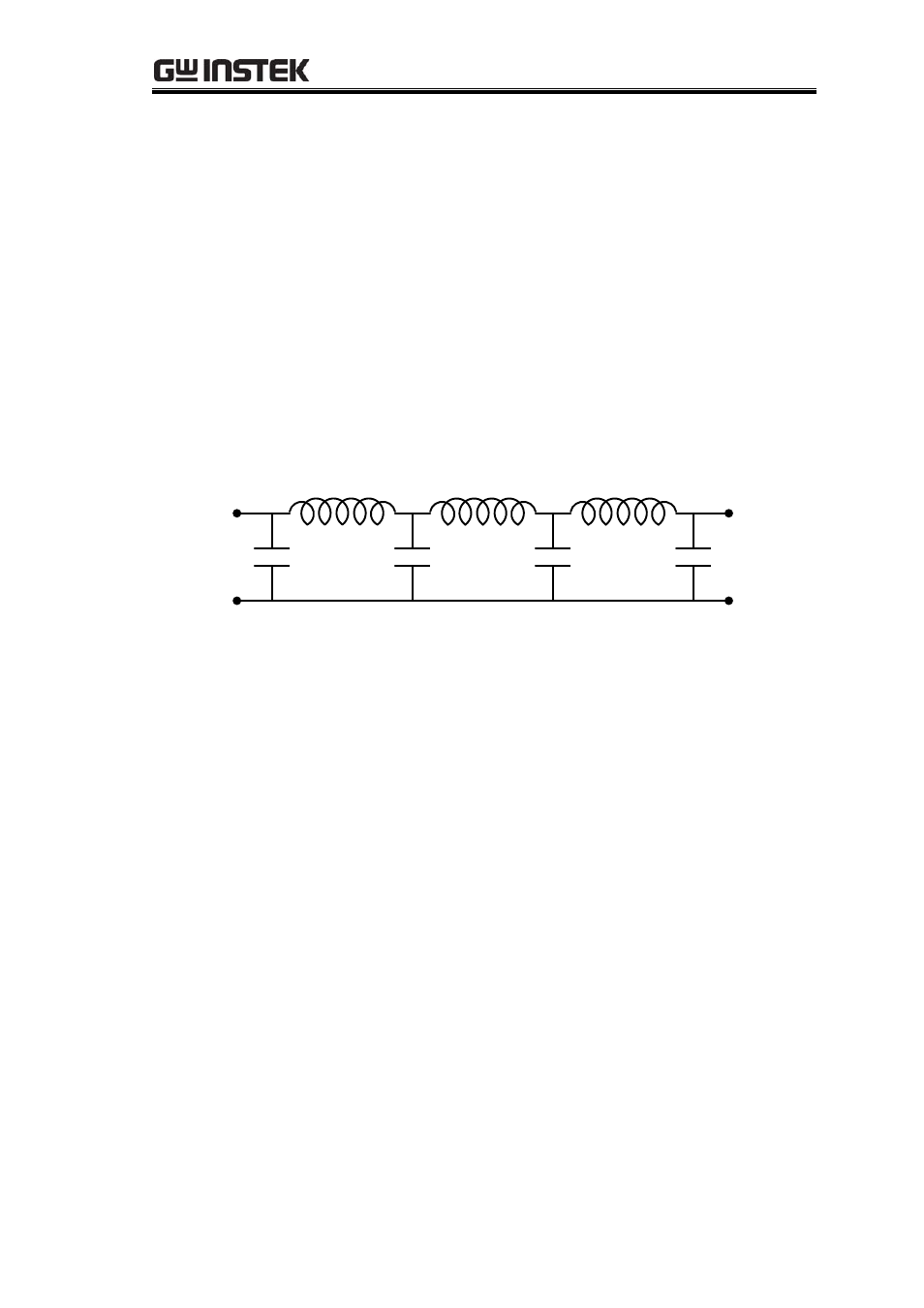
The equivalent circuit is illustrated in Figure 16-5.
4
L
5
C
7
C
6
L
3
C
2
L
1
C
Figure 16-5
We then convert the L, C value to electronic length by the following equations:
E
L
=LRo/Z
h
, for inductor
(16-21)
E
L
=CZ
l
/Ro , for capacitor
(16-22)
Ro is the filter impedance,
E is the wave number,
L
is the line length, L and C are
the normalized values, Z
h
and Z
l
are the highest and lowest line impedance, respectively.
According to Figure 16-3, g1, g3, g5 and g7 are capacitor sections in Z
l
, and g2,
g4 and g6 are inductor sections in Z
h
.
The PCB substrate is 1.2 mm thick, FR4 material,
H
r
= 4.4. In order to make the
PCB fabrication realistic, the line widths are adjusted to 0.5mm for Z
h
and 5mm for Z
l
before we start designing. The item left to be designed is the length of each section.
- GDB-03 (99 pages)
- GLA-1000 Series User Manual (111 pages)
- GLA-1000 Series Quick start guide (20 pages)
- GOS-630FC (20 pages)
- GOS-635G (36 pages)
- GOS-6000 Series (27 pages)
- GOS-6103C (30 pages)
- GOS-6100 Series (30 pages)
- GRS-6000A Series (51 pages)
- GDS-122 Installation Guide (4 pages)
- GDS-122 User Manual (52 pages)
- GDS-2000A series CAN/LIN bus User Manual (18 pages)
- GDS-2000A series Quick start guide for DS2-FGN (6 pages)
- GDS-2000A series Freewave User Manual (26 pages)
- GDS-2000A series Quick start guide for Logic analyzer option (18 pages)
- GDS-2000A series Quick start quide for DS2-LAN (2 pages)
- GDS-2000A series Option User Manual (80 pages)
- GDS-2000A series User Manual (261 pages)
- GDS-2000A series Programming Manual (272 pages)
- GDS-2000A series Single sheet for LA Quick start guide (2 pages)
- GBS-1000 Series Programming Manual (88 pages)
- GBS-1000 Series User Manual (187 pages)
- GDS-1000-U Series firmware upgrade (1 page)
- GDS-1000-U Series Programming Manual (70 pages)
- GDS-1000-U Series Quick start guide (2 pages)
- GDS-1000-U Series User Manual (133 pages)
- GDS-1000A-U Series Programming Manual (88 pages)
- GDS-1000A-U Series Quick start guide (2 pages)
- GDS-1000A-U Series User Manual (148 pages)
- GDS-3000 Series GCP-530/1030 current probe User Manual (40 pages)
- GDS-3000 Series GDP-025/050/100 differential probe User Manual (21 pages)
- GDS-3000 Series DS3-PWR Power analysis manual (37 pages)
- GDS-3000 Series User Manual (209 pages)
- GDS-3000 Series Programming Manual (103 pages)
- GDS-3000 Series DS3-SBD Serial Bus decode (29 pages)
- GDS-3000 Series GKT-100 deskew fixture User Manual (1 page)
- GDS-3000 Series GUG-001, GPIB to USB adapter User Manual (15 pages)
- GDS-300 Series User Manual (188 pages)
- GDS-300 Series Programming Manual (139 pages)
- GDS-300 Series Quick start guide (21 pages)
- GRF-3300 Series Student Manual (26 pages)
- GRF-1300A (124 pages)
- GSP-810 User Manual (40 pages)
- GSP-810 Software Manual (3 pages)