GW Instek GDS-1000A-U Series Quick start guide User Manual
Page 2
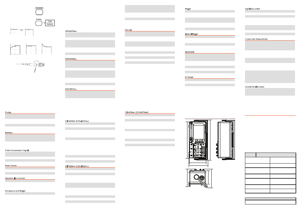
8. Press the Autoset key. A
square waveform will
appear in the center of the
display.
9. Press the Display key, then
Type and select the vector
waveform type.
10. Turn the adjustment point on the probe to flatten
the square waveform edge.
Over
Compensation
Normal
Under
Compensation
11. Setting up the oscilloscope is complete. You may
start to use the oscilloscope.
S
PECIFICATIONS
The specifications apply when the oscilloscope is
powered on for at least 30 minutes under +20°C~+30°C.
Model Specific Specifications
GDS-1072A-U
Bandwidth (–3dB)
DC coupling: DC ~ 70MHz
AC coupling: 10Hz ~ 70MHz
Bandwidth Limit
20MHz (−3dB)
Trigger Sensitivity
0.5div or 5mV (DC ~ 25MHz)
1.5div or 15mV
(25MHz~70MHz)
External Trigger
Sensitivity
~ 50mV (DC~25MHz)
~ 100mV (25MHz~70MHz)
Rise Time
< 5.8ns approx.
GDS-1102A-U
Bandwidth (–3dB)
DC coupling: DC ~ 100MHz
AC coupling: 10Hz ~
100MHz
Bandwidth Limit
20MHz (−3dB)
Trigger Sensitivity
0.5div or 5mV (DC ~ 25MHz)
1.5div or 15mV
(25MHz~100MHz)
External Trigger
Sensitivity
~ 50mV (DC~25MHz)
~ 100mV (25MHz~100MHz)
Rise Time
< 3.5ns approx.
GDS-1152A-U
Bandwidth (–3dB)
DC coupling: DC ~ 150MHz
AC coupling: 10Hz ~
150MHz
Bandwidth Limit
20MHz (−3dB)
Trigger Sensitivity
0.5div or 5mV (DC ~ 25MHz)
1.5div or 15mV
(25MHz~150MHz)
External Trigger
Sensitivity
~ 50mV (DC~25MHz)
~ 100mV (25MHz~100MHz)
Rise Time
< 2.3ns approx.
Common Specifications
Vertical
Sensitivity
2mV/div~10V/Div (1-2-5
increments)
Accuracy
± (3% x |Readout|+0.1div +
1mV)
Bandwidth
See model-specific
specifications
Rise Time
See model-specific
specifications
Input Coupling
AC, DC, Ground
Input Impedance
1MΩ±2%, ~15pF
Polarity
Normal, Invert
Maximum Input
300V (DC+AC peak), CAT II
Math Operation
+, –, ×, FFT, FFT rms
Offset Range
2mV/div~50mV/div: ±0.4V
100mV/div~500mV/div:
±4V
1V/div~5V/div: ±40V
10V/div : ±300V
Trigger
Sources
CH1, CH2, Line, EXT
Modes
Auto, Normal, Single, TV,
Edge, Pulse
Coupling
AC, DC, LF rej, HF rej, Noise
rej
Sensitivity
See model-specific
specifications
Holdoff
40ns ~ 2.5s
External Trigger
Range
DC: ±15V, AC: ±2V
Sensitivity
See model-specific
specifications
Input Impedance
1MΩ±2%, ~15pF
Maximum Input
300V (DC+AC peak), CATII
Horizontal
Range
1ns/div~50s/div, 1-2.5-5
increment
Roll: 50ms/div – 50s/div
Modes
Main, Window, Window
Zoom, Roll, X-Y
Accuracy
±0.01%
Pre-Trigger
10 div maximum
Post-Trigger
1000 div
X-Y Mode
X-Axis Input
Channel 1
Y-Axis Input
Channel 2
Phase Shift
±3° at 100kHz
Signal Acquisition
Real-Time
1G Sa/s maximum
Equivalent
25G Sa/s maximum
Vertical Resolution
8 bits
Record Length
Maximum; 2M points (1
channel), 1M points (2
channels)
Acquisition
Normal, Peak Detect,
Average
Peak Detection
10ns (500ns/div ~ 50s/div)
Average
2, 4, 8, 16, 32, 64, 128, 256
Cursors and Measurement
Voltage
Vpp, Vamp, Vavg, Vrms,
Vhi, Vlo, Vmax, Vmin, Rise
Preshoot/ Overshoot, Fall
Preshoot/ Overshoot
Time
Freq, Period, Rise Time, Fall
Time, + Width, – Width,
Duty Cycle
Delay
FRR, FRF, FFR, FFF, LRR,
LRF, LFR, LFF
Cursors
Voltage difference (ΔV) and
Time difference (ΔT) between
cursors
Auto Counter
Resolution: 6 digits,
Accuracy: ±2%
Signal source: All available
trigger source except the
Video trigger
Control Panel Function
Autoset
Automatically adjust Vertical
Volt/div, Horizontal
Time/div, and Trigger level
Save/Recall
Up to 15 sets of measurement
conditions and waveforms
Display
LCD
5.6 inch, TFT, brightness
adjustable
Resolution (dots)
234 (Vertical) x 320
(Horizontal)
Graticule
8 x 10 divisions
Display Contrast
Adjustable
Interface
USB Slave Connector
USB1.1 & 2.0 full speed
compatible (flash disk not
supported)
USB Host connector
Image (BMP) and waveform
data (CSV)
Probe Compensation Signal
Frequency range
1kHz ~ 100kHz adjustable,
1kHz step
Duty cycle
5% ~ 95% adjustable, 5% step
Amplitude
2Vpp±3%
Power Source
Line Voltage
100V~240V AC, 47Hz~63Hz
Power Consumption
18W, 40VA maximum
Fuse Rating
1A slow, 250V
Operation Environment
Storage Temperature
-10°C~60°C, no condensation
Relative humidity
93% @ 40°C
65% @ 41°C~60°C
Dimensions and Weight
Dimensions
310(W) x 142(H) x 140(D) mm
Weight
Approx. 2.5kg
Probe Specifications
GTP-150A-2 (GDS-1152A-U)
Probe Position
Position x10 Position x1
Attenuation Ratio
10:1
1:1
Bandwidth
DC ~ 150MHz DC~6MHz
Input Resistance
10MΩ when
used with
1MΩ input
1MΩ when
used with
1MΩ input
Input Capacitance
17pF approx. 47pF approx.
Maximum Input Voltage
500V CAT I,
300V CAT II
(DC+Peak
AC) Derating
with
frequency
300V CAT I,
150V CAT II
(DC+Peak
AC) Derating
with
frequency
Temperature
–10°C ~ 55°C
Relative Humidity
≤85% @35°C
Safety Standard
EN 61010-031 CAT II
GTP-100A-4 (GDS-1102A-U)
Probe Position
Position x10 Position x1
Attenuation Ratio
10:1
1:1
Bandwidth
DC ~ 100MHz DC~6MHz
Input Resistance
10MΩ when
used with
1MΩ input
1MΩ when
used with
1MΩ input
Input Capacitance
14.5~17.5pF
approx.
85~115pF
approx.
Maximum Input Voltage
≤600Vpk,
Derating with
frequency
≤200Vpk,
Derating with
frequency
Temperature
–10°C ~ 50°C
Relative Humidity
≤85% @35°C
Safety Standard
EN 61010-031 CAT II
GTP-070A-4 (GDS-1072A-U)
Probe Position
Position x10 Position x1
Attenuation Ratio
10:1
1:1
Bandwidth
DC ~ 70MHz DC~6MHz
Input Resistance
10MΩ when
used with
1MΩ input
1MΩ when
used with
1MΩ input
Input Capacitance
28pF~32pF
120pF~220pF
Maximum Input Voltage
≤600Vpk,
Derating with
frequency
≤200Vpk,
Derating with
frequency
Temperature
–10°C ~ 50°C
Relative Humidity
≤85%
Safety Standard
EN 61010-031 CAT II
Dimensions
VI
D/
E
MI
T
VI
D/
ST
L
O
V
VI
D/
ST
L
O
V
U
N
E
M
U
N
E
M
2
H
C
HT
A
M
1
H
C
A
cq
uir
e
Di
sp
la
y
U
tili
ty
H
elp
R
un
/S
to
p
VA
R
IAB
LE
FO
RC
E
A
uto
se
t
C
urs
or
S
IN
G
LE
H
ard
cop
y
M
ea
su
re
S
ave
/R
eca
ll
LEVE
L
RE
G
GI
RT
L
AT
N
OZ
I
R
O
H
LA
CI
T
RE
V
CH
1
CA
T
30
0V M
15
pF
M
AX
. 3
00
Vp
k
1
CH
2
EX
T
TR
IG
C
AT
30
0V M
15
pF
M
AX
. 3
00
V
pk
1
Y
X
310.
0
341.
5
142.0
162.3
115.
1
14
9.
0
159.
0
150
MH
z
1
G
Sa
/s
D
igi
ta
l St
orage
O
sc
illo
sc
op
e
G
D
S-1
15
2A
-U
EC Declaration of Conformity
We
GOOD WILL INSTRUMENT CO., LTD.
No.7-1, Jhongsing Rd., Tucheng Dist., New Taipei City 236,
Taiwan
GOOD WILL INSTRUMENT (SUZHOU) CO., LTD.
No. 69, Lushan Road, Suzhou New District Jiangsu, China
declares that the below mentioned product
GDS-1072A-U, GDS-1102A-U, GDS-1152A-U
Are herewith confirmed to comply with the requirements set
out in the Council Directive on the Approximation of the Law
of Member States relating to Electromagnetic Compatibility
(2004/108/EC) and Low Voltage Equipment Directive
(2006/95/EC). For the evaluation regarding the
Electromagnetic Compatibility and Low Voltage Equipment
Directive, the following standards were applied:
◎ EMC
EN 61326-1 :
EN 61326-2-1:
Electrical equipment for measurement, control and
laboratory use –– EMC requirements (2006)
Conducted and Radiated
Emissions
CISPR11: 2003+A1: 2004+A2: 2006
Electrostatic Discharge
IEC 61000-4-2: 2001
Current Harmonic
EN 61000-3-2: 2006
Radiated Immunity
IEC 61000-4-3: 2006+A1: 2007
Voltage Fluctuation
EN 61000-3-3: 1995+A1: 2001+A2 :
2005
Electrical Fast Transients
IEC 61000-4-4: 2004+Corr.1 :
2006+Corr.2 : 2007
-------------------------
Surge Immunity
IEC 61000-4-5: 2005
-------------------------
Conducted Susceptibility
IEC 61000-4-6: 2003+A1: 2004+A2:
2006
-------------------------
Power Frequency Magnetic Field IEC
61000-4-8: 2001
-------------------------
Voltage Dips/ InterruptsIEC 61000-
4-11: 2004
◎ Safety
Low Voltage Equipment Directive 2006/95/EC
Safety Requirements
IEC/EN 61010-1: 2001