Figure #6, Figure #5a – Detcon IR-642 User Manual
Page 13
Material Requirements
*
Detcon PN 3270 MicroSafe™ Programming Magnet
*
Digital volt/ohm meter.
3.6.2 Programming Magnet Operating Instructions
Operator interface to MicroSafe™ gas detection products is via magnetic switches located behind the transmitter
face plate. DO NOT remove the glass lens cover to calibrate or change programming parameters. Two switches
labeled “PGM 1” and “PGM 2” allow for complete calibration and alarm level programming without removing the
enclosure cover, thereby eliminating the need for area de-classif ication or the use of hot permits.
A magnetic programming tool (see f igure 6) is used to operate the switches. Switch action is def ined as momentary
contact, 3 second hold, and 30 second hold. In momentary contact use, the programming magnet is waved over a
switch location. In 3 second hold, the programming magnet is held in place over a switch location for 3 or more
seconds. In 30 second hold, the programming magnet is held in place over a switch location for 30 or more sec-
onds. Three and thirty second hold is used to enter or exit calibration and program menus while momentary con-
tact is used to make adjustments. The location of “PGM 1” and “PGM 2” are shown in f igure 7.
NOTE: If, after entering the calibration or program menus, there is no interaction with the menu items for more
Detcon Model IR-640/IR-642 Carbon Dioxide Sensor PG.13
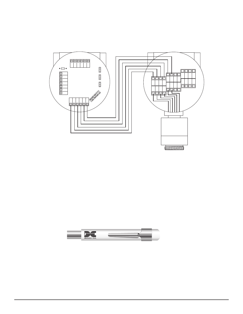
Magnetic Programming Tool
Figure #6
1 2 3 4
R
E
D
B
R
N
W
H
T
B
LK
Remote Transmitter
IR-640-RT
Remote Sensor
IR-640-RS
W
H
T
B
L
K
Y
E
L
B
LU
R
E
D
B
R
N
5 6
Y
E
L
B
LU
Figure #5A