Figure #5, Figure #4 – Detcon IR-642 User Manual
Page 11
tact outputs: NO = Normally Open; NC = Normally closed (see f igure 3).
Note: If a voltage signal output is desired in place of the 4-20mA output, a 1/4 watt resistor must be installed
in position R2 of the terminal board. A 250
Ω resistor will provide a 1-5V output (– to mA). A 100Ω resistor will
provide a .4-2V output, etc. This linear signal corresponds to 0-100% of full-scale (see f igure 3).
e)
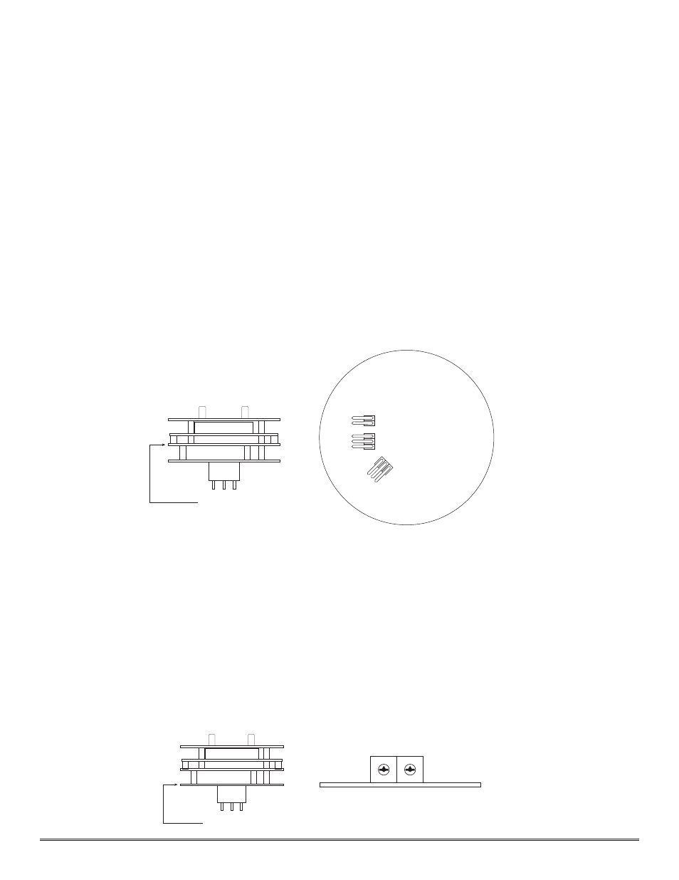
Program the alarms via the gold plated jumper tab positions located on the CPU board (see f igure 4). Alarm 1
and Alarm 2 have three jumper programmable functions: latching/non-latching relays, normally energized/nor-
mally de-energized relays, and ascending/descending alarm set points. The fault alarm has two jumper program-
mable functions: latching/non-latching relay, and normally energized/normally de-energized relay. The default
settings of the alarms (jumpers removed) are normally de-energized relays, non-latching relays, and alarm points
that activate during descending gas conditions.
If a jumper tab is installed in the latch position, that alarm relay will be in the latching mode. The latching
mode will latch the alarm after alarm conditions have cleared until the alarm reset function is activated. The non-
latching mode (jumper removed) will allow alarms to de-activate automatically once alarm conditions have cleared.
If a jumper tab is installed in the energize position, that alarm relay will be in the energized mode. The ener-
gized mode will energize or activate the alarm relay when there is no alarm condition and de-energize or de-acti-
vate the alarm relay when there is an alarm condition. The de-energized mode (jumper removed) will energize or
activate the alarm relay during an alarm condition and de-energize or de-activate the alarm relay when there is
no alarm condition.
If a jumper tab is installed in the ascending position, that alarm relay will be in the ascending mode. The
ascending mode will cause an alarm to f ire when the gas concentration detected is greater than or equal to the
alarm set point. The descending mode (jumper removed) will cause an alarm to f ire when the gas concentration
detected is lesser than or equal to the alarm set point. Except in special applications, CO2 monitoring will
require alarms to f ire in “ASCENDING” gas conditions.
Any unused jumper tabs should be stored on the connector board on the terminal strip labeled “Unused
Jumpers” (see f igure 3).
f)
If applicable, set the RS-485 ID number via the two rotary dip switches located on the preamp board (see f igure
5). There are 256 different ID numbers available which are based on the hexadecimal numbering system. If RS-
485 communications are used, each sensor must have its own unique ID number. Use a jewelers screwdriver to
set the rotary dip switches according to the hexadecimal table listed below. If RS-485 communications are not
used, leave the dip switches in the default position which is zero/zero (0)-(0).
Detcon Model IR-640/IR-642 Carbon Dioxide Sensor PG.11
Preamp Board - Side View
RS-485 ID Set Dip Switches
Control Circuit - Side View
Preamp Board
0 12
3
4
5
6
78
9A
B
C
D
E
F
0 12
3
4
5
6
78
9A
B
C
D
E
F
SW2
SW1
Figure #5
FAULT
ALARM 1
Latch
Energize
Latch
Ascending
Energize
A
LA
R
M
2
La
tc
h
A
sc
en
di
ng
E
ne
rg
iz
e
CPU Board - Top View
Alarm Programming Jumpers
Control Circuit - Side View
CPU Board
Figure #4