WEN 70712 12 Sliding Compound Miter Saw User Manual
Page 17
ITEM 70712 OPERATOR’S MANUAL 17
Squaring the Saw Blade to the Guide Fence
WARNING: Be sure that the Miter Saw is switched OFF and unplugged from the power source
before performing any work on the tool. Failure to unplug the saw may result in accidental start-
up, causing possible serious bodily injury.
1. Unplug the Miter Saw.
2. Loosen the Miter Lock Knob. Rotate the Miter Table and move pointer to the 0º
position.
3. Tighten the Miter Lock Knob securely.
4. Pull the saw head down completely and lock the saw head into the transport position.
5. Lay a small framing square or tri-square on the Miter Table. Place one leg of the square
against the Guide Fence and slide the other leg of the square against a flat part of the Saw
Blade. (Be sure the square contacts the flat part of the Saw Blade and not the blade teeth.)
6. Check that the edge of the square and the Saw Blade are parallel along the entire length of
the square's edge.
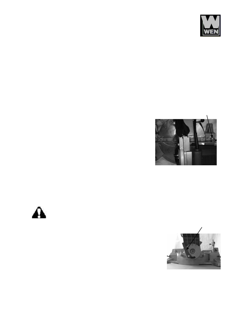
7. If the front or back portion of the blade angles away from
the squarer's edge, adjusting the Guide Fence is necessary.
8. Using the Allen wrench, loosen the two hex bolts (Fig. 3)
that secure the Guide Fence to the saw's stationary table.
9. While holding one leg of the square against the Guide
Fence, slowly move the Guide Fence to the left or right
until the Saw Blade is parallel with square's other leg.
10. Carefully tighten the two hex bolts and recheck the blade
alignment as in steps 5 and 6.
0º and 45º Bevel Stop Adjustments
NOTE: This is factory set and usually does not require adjusting. (This saw may not come with
the necessary tools for the following procedure.)
WARNING: Be sure that the tool is switched OFF and unplugged from the power
source before performing any work on the tool. Failure to unplug the saw may result
in accidental start-up, causing possible serious bodily injury.
1. Unplug the Miter Saw.
2.
Align the Miter Table to 0º
and lock the saw head down in the
transport position.
3. Loosen the Bevel Lock Knob (Fig. 4) at the rear of the saw by
turning it counter-clockwise and set the Saw Arm at 0º
bevel
(blade 90º
to the Miter Table).
4. Place a combination square on the Miter Table and the flat part
of the Saw Blade (making sure the square is not touching any blade teeth).
Bolt
Fig. 3
Fig. 4
Bevel lock handle