Section 3 - specifications – Van Air Systems HLSXA-55 User Manual
Page 3
PAGE 3
3.1 DRYER SPECIFICATIONS
DIMENSIONS .....................See SECTION 3.2
VESSELS (desiccant towers)
Construction ................... Manufactured to ASME CODE, Section VIII, Div. 1.
Vessels stamped "UM" designator.
Design Pressure ............. 300 PSIG
Design Temperature ....... -20
O
F TO 200
O
F
PIPING
Threaded fittings: ANSI B16.11
Threaded unions: ANSI B16.11
Pipe: Carbon steel, Schedule 40
VALVES
Inlet ............................... 4-Way ball valve w/ actuator (Qty. 1)
Outlet .............................. Check valves (Qty. 2)
Purge .............................. Ball valve w/ actuator N.C. (Qty. 1)
Purge Metering .............. Needle valve (Qty. 1)
CONTROL AIR FILTER
Construction ................... Aluminum housing
ELECTRICAL
Voltage ........................... 115V/1PH/60HZ
CONTROL BOX
NEMA 4/7 CD
Explosion Proof (Class 1, Div 1, Groups C & D)
DESICCANT
Material ........................................... Activated Alumina, 1/8" (2-5 MM) Bead type
Quantity Per Tower: ........................ See SECTION 3.2
OPERATING CONDITIONS
Inlet Operating Pressure ................ MIN 80 PSIG ...........MAX 250 PSIG
Inlet Operating Temperature ........... MIN 40
O
F ................MAX 120
O
F
Ambient Operating Temperature .... MIN 40
O
F ................MAX 120
O
F
PROCESS GAS
Compressed Air
RATED INLET CONDITIONS
Inlet Air Pressure ............................ 100 PSIG
Inlet Air Temperature ...................... 100°F
Relative Humidity (saturation) ........ 100% RH
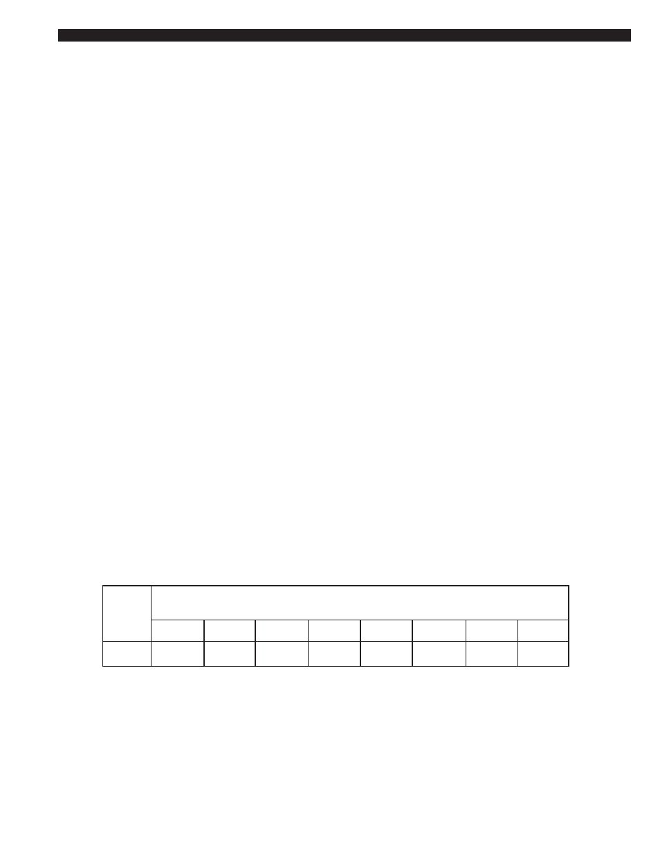
RATED FLOW CAPACITIES
SPECIFICATIONS
SECTION 3
MODEL
HLSXA55
80 PSIG
45
Flow capacities at various pressures
SCFM
100 PSIG
55
125 PSIG
61
150 PSIG
66
175 PSIG
71
200 PSIG
75
225 PSIG
80
250 PSIG
84