Operating, Dismantling & assembly instructions, Reassembly – Universal Air Tools UT8735 User Manual
Page 2: Safety rules when using a die grinder
Operating
Select a suitable mounted point that has a free running speed higher
than the maximum running speed marked on the tool. Make sure that
the diameter of the shank exactly matches the diameter of the collet
mounted in the grinder. There are four standard sizes of collet available
for use with this grinder, i.e.
1) - 1/4" Dia (0.250ins) (6.35mm)
2) - 6mm (0.236ins)
3) - 1/8" (0.125ins) (3.175mm)
4) - 3mm (0.118ins)
Never try to force a 1/4" diameter shank into a 6mm collet or a 1/8"
diameter shank into a 3mm collet. Never try to close a 1/4" diameter
collet to secure a 6mm shank or a 1/8" diameter collet to secure a
3mm diameter shank. Always match correctly the shank size to the
collet size. If uncertain, have parts measured by a competent person.
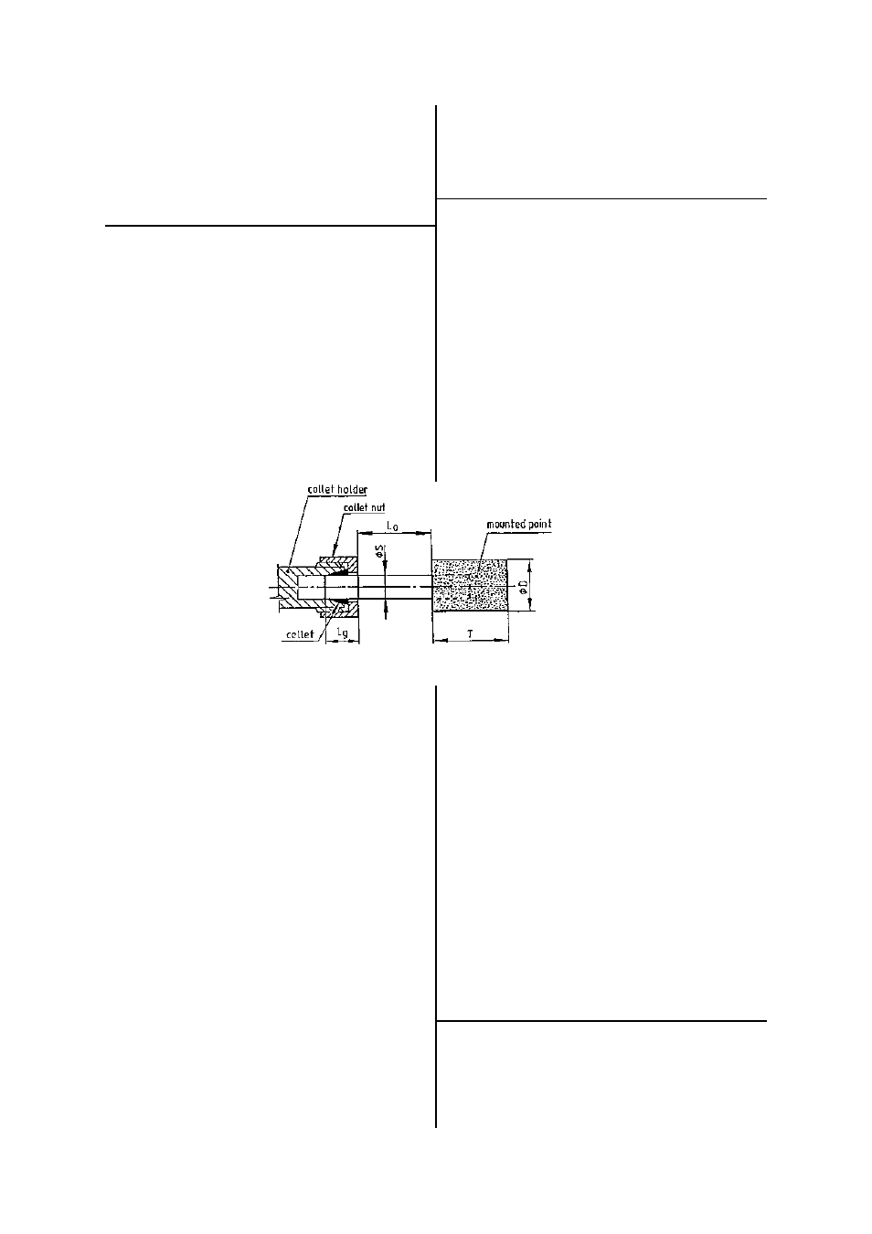
Push the shank as far as possible into the collet and tighten the collet nut
using the spanners provided on
the collet nut and output spindle.
The shank of the mounted point
may be pulled forward from the
maximum insertion length but
always ensure a minimum
gripping length of not less than
10mm - See Figure 2.
Be aware that the allowed
running speed of the mounted
point is lowered because of an
increase in the length of the shank
between the end of the collet and
the body of the mounted point.
This distance is shown in Diagram
2 as "LO" and is called the
overhang. The information with respect to mounted point size,
permissible running speed and reduction in running speed due to an
increase in overhang is available from the supplier of the mounted point.
If the increase in overhang for access reasons takes the permissible
running speed of the mounted point below the free running speed of
the grinder select a smaller diameter mounted point.
The fitting of the mounted point should be done by a trained operator.
When first starting the grinder with a new wheel fitted, the grinder
should not be near other persons and be held in a protected area, i.e.
under a bench and run for a few seconds. This will protect personnel
from possible effects of damage to the mounted point before it was
fitted to the grinder i.e. wheel breakage.
Always use eye protection and wear protective gloves if there are sharp
edges in the work area. The tool and the grinding process can create a
noise level such that the use of ear protectors is advised.
If the grinding process creates a dust then use a suitable breathing
mask.
Check that the material being worked will not cause harmful dust or
fumes. If this is so then special breathing masks may be required.
If the grinder vibrates when first fitting a mounted point or during
operation, remove from service immediately and correct fault before
continuing to use.
Do not apply excessive pressure as this will reduce the cutting efficiency
and can bend the shank of the mounted point causing vibration and the
possibility of breakage. Apply light loads to allow the wheel to cut.
Handle the grinder with care. If the grinder is dropped, carefully check
the mounted point for damage, i.e. cracks, chipping and start for the
first time as for fitting a new wheel i.e. under a bench.
Never exceed the maximum air pressure. If there is this possibility
always use this grinder with a pressure reducing valve fitted in the
Dismantling & Assembly Instructions
Disconnect from air supply.
Remove collet nut (75) and collet (76). Grip the motor housing (1) on
the flats at air inlet end in a vice with soft jaws and unscrew inlet bushing
(82) and remove screen (44). With a sharp pointed tool lever out
retaining ring (32) and pull out exhaust deflector (30).
Tap out pin (36) and remove safety lever (18). Do not dismantle safety
lever (18) unless replacements are required.
Unscrew valve screw (22) and remove O-Ring (35), O-Ring (34), air
regulator (21), valve spring (39), valve stem(20) and O-Ring (33).
Unscrew coupling nut (14) and remove extended front end assembly
complete.
To dismantle extended front end assembly, coupling nut (14) may be
unscrewed from extension housing (71) [left hand thread].
Grip extension housing (71) on the flats in a vice and unscrew spindle
nut (73) [left hand thread]. Pull out spindle and bearing assembly and
grip on the hexagon of drive nut (16) and unscrew extension shaft (72)
using the flats on the extension shaft. Bearings (79) and (80) may be
tapped off of extension spindle (72).
Remove coupling (24) and pin (38) assembly
and pin (38) may be tapped out of coupling
(24). Unscrew lock ring (15) complete with O-
Ring (81). Pull out motor assembly.
Grip the motor assembly by hand or in a soft
jaw vice and tap the rear end of the rotor (3)
through the rear end plate (4) and bearing
(40). Tap rear end bearing (40) out of rear end plate (4). Remove 5 off
rotor blades (5) and remove cylinder (2). Pins (37) may be removed
from cylinder (2). Grip rotor (3) in a soft jaw vice and unscrew drive nut
(16). The rotor (3) can then be tapped through front end bearing (41),
shim (27), front end plate (17) and collar (23). Front end bearing (41)
can be tapped out of front end plate (17) and shim (27) can be
removed.
Clean and examine parts for wear and replace only with manufacturer
supplied parts. Ensure that the faces of end plates (4) and (17) that abut
cylinder (2) are flat and free from burrs. Lap on a flat, very fine grade of
abrasive paper if necessary. Check O-Rings for cuts and wear.
Reassembly
Lightly coat parts with oil, pack bearings with a lithium or molybdenum
based general purpose grease and reassemble in the reverse order.
Note:- when reassembling the motor assembly, ensure that pins (37) in
cylinder (2) are correctly located in the holes in front end plate (17) and
rear end plate (4). Also ensure that pin (83) located in the outside
diameter of front end plate (17) locates in the slot in motor housing (1).
Check the collet assembly, the function of the safety lever and that the
free speed is correct before returning to service. Ensure that the air
regulator is in the maximum open position before making a speed
check.
incorporating a rust inhibitor. Reconnect tool to air supply and run tool
slowly for a few seconds to allow air to circulate the oil. If tool is used
frequently lubricate on daily basis and if tool starts to slow or lose power.
It is recommended that the air pressure at the tool whilst the tool is
running is 90 p.s.i./6.3 bar. The tool can run at lower and higher
pressures with the maximum permitted working air pressure of 100
p.s.i./7.0 bar.
Page No 2
supply line. Your supplier will advise of suitable equipment.
This grinder is fitted with a speed regulator and the speed may be
reduced by rotating air regulator (21) with a suitable screwdriver. When
making speed checks always rotate the air regulator to the position to
give the highest maximum speed.
D
= diameter of mounted point
T
= length of mounted point
Lo
= overhang
S
= diameter of shank
Lg
= gripping length
Figure 2. Gripping length of collet and chuck
Safety Rules When Using A Die Grinder
1) Read all the instructions before using this tool. All operators must be
fully trained in its use and aware of these safety rules.
2) Always select suitable abrasive to use with this tool - see Operating
Instructions.