Ft7000 edu a, Installation of the edu tray and mounting hardware – Triton FT7000 EDU Installation Manual User Manual
Page 7
7
M
oDEl
Ft7000 EDU a
ssEMbly
F
iElD
i
nstallation
G
UiDE
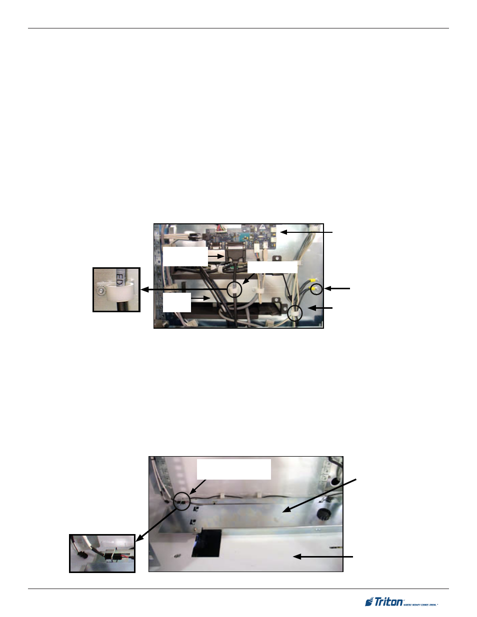
Installation of the EDU Comms/Power and UCV4 Ground Cables (Cabinet Side)
1. Refer to the Figure below. Remove the Rear Service Panel (RSP) cables from the white cable
hanger (directly below the approximate center of the main GPIO PCB). Loosen and rotate the
cable hanger 180 degrees (so the opening in the cable hanger is to the rear of the cabinet).
Tighten the mounting screw for the cable hanger.
2. Press the EDU Comms/Power cable into the white cable hanger and plug it into the main GPIO
PCB (J4).
3. Locate the four (4) grounding studs to the right of the cable hanger used for the EDU Comms/
Power cable. Press the UCV4 Ground cable into the white cable hanger below the grounding
studs. Connect the UCV4 Ground cable to an open grounding stud with an #8 x 32” nut.
5. Slide the EDU Depository Bin into the EDU Depository Bin Mounting Bracket.
Installation of the EDU Tray and Mounting Hardware
UCV Vertical Assembly (includes the Right Hand Slide and E-Chain):
1. Refer to the Figures below. Lay the UCV Vertical Assembly on the bottom of the I/O Bay (upside
down with the micro-switch to the front of the cabinet.
2. There are two cables hanging down at the front right corner of the I/O Bay. Select the cable
marked “ UCV4” and plug it into the micro-switch on the UCV Vertical Assembly.
UCV4 Ground
Cable
Gpio pCb
i/o b
ay
(U
ppEr
)
Cable Hangers
EDU Power/
Comms Cable
RSP
Cables
i/o b
ay
(
lowEr
)
UCv v
ErtiCal
a
ssEMbly
UCV4 connection to the
UCV Vertical Assembly