Agri-Fab Tine De-Thatcher 45-02951 User Manual
Page 5
5
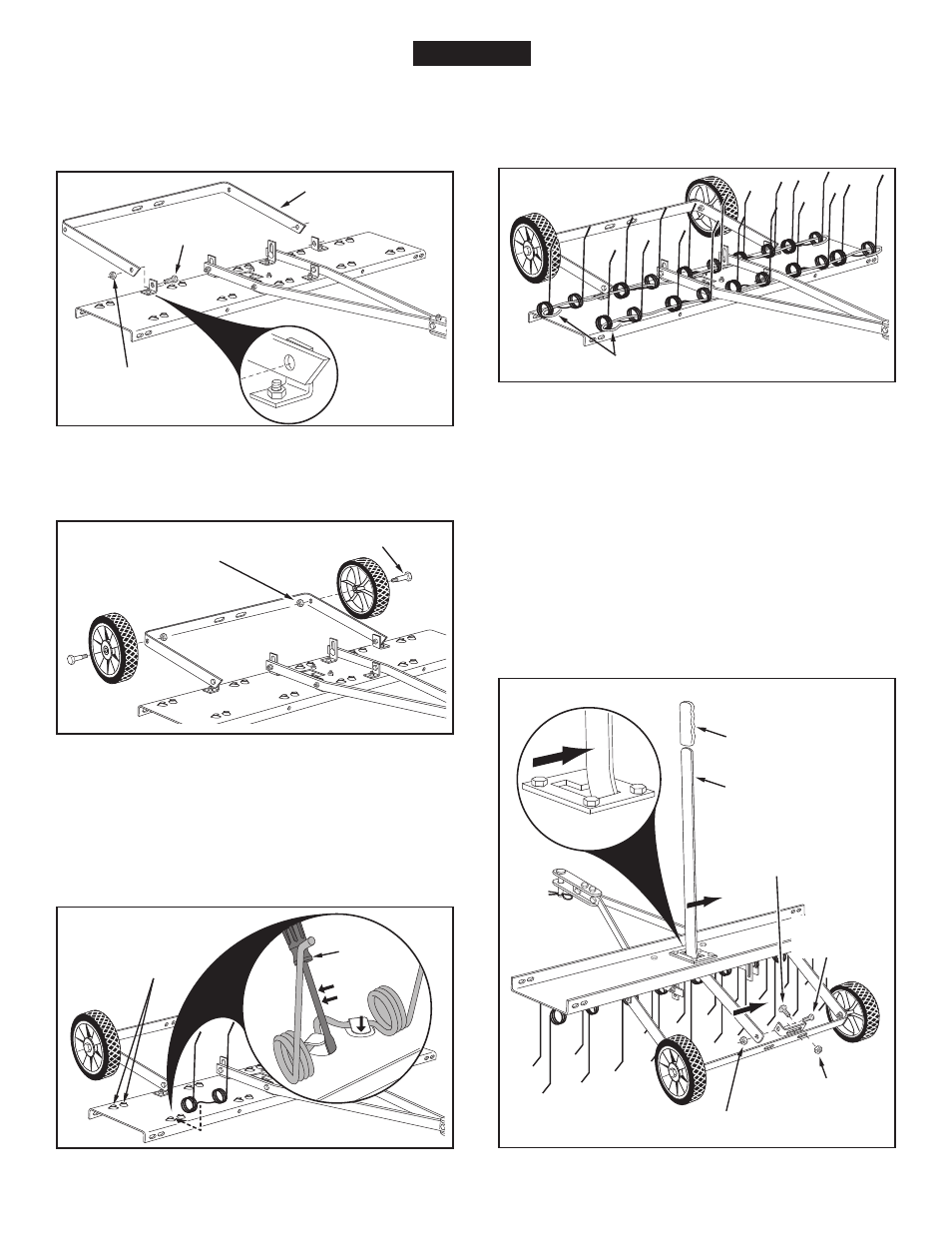
11. Assemble the axle bracket on the outside of the angle
brackets using two 5/16" x 1" hex bolts and 5/16"
nylock nuts. The ends of the axle bracket must point
as shown in figure 5.
Tighten and then loosen the
bolts and nuts slightly.
FIGURE 5
FIGURE 7
13. Starting with the front row of tabs, slide a spring tine
under a set of tabs. Insert a screw driver or punch
down into the tray and bend each tab until the end
of the tab is bent down even with the surface of the
tray. Repeat to attach all spring tines. See figure 7.
NOTE: Slight looseness of the spring tines under the bent
tabs is normal.
FIGURE 6
12. Assemble the wheels to the axle bracket using two
shoulder bolts and two 3/8" nylock nuts.
Tighten. See
figure 6.
14. Assemble the spring align wires through the front and
rear rows of spring tines, passing the wires in between
the hitch mount arms and the tine shield. Bend the
ends of the wires to secure them. See figure 8.
FIGURE 9
15. Assemble a hitch arm mount bracket to the axle bracket
using two 5/16" x 1" carriage bolts, and 5/16" nylock
nuts.
Do not tighten yet. See figure 9.
16. Insert the lift handle down through the tine shield. Attach
it to the just assembled hitch arm mount bracket using
a 5/16" x 1" hex bolt and a 5/16" nylock nut.
Tighten.
See figure 9.
17. Position the hitch arm mount bracket so that there is
side tension on the lift handle when it is locked in the
up position.
Tighten the nuts. See figure 9.
18. Assemble the grip onto the end of the lift handle. See
figure 9.
FIGURE 8
5/16" NYLOCK NUT
5/16" x 1"
HEX BOLT
AXLE BRACKET
3/8" NYLOCK NUT
SHOULDER BOLT
SPRING ALIGN WIRE
LIFT HANDLE
GRIP
5/16" NYLOCK NUT
5/16" x 1"
HEX BOLT
5/16"
NYLOCK
NUT
5/16" x 1"
CARRIAGE BOLT
ENGlISH
TABS
SCREW
DRIVER