Star Water Systems S1203 User Manual
Page 7
12
13
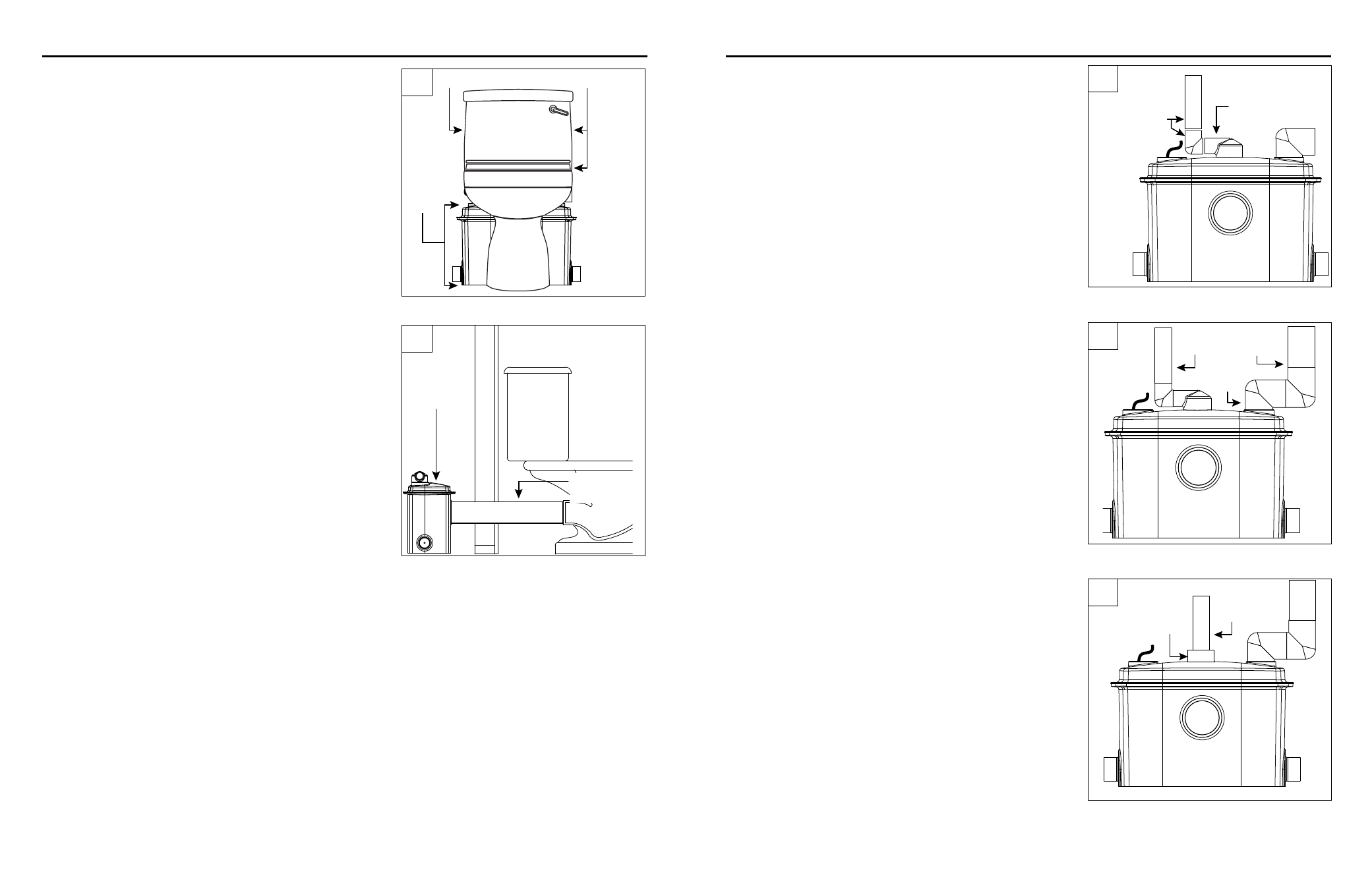
NOTE: Installing the grinder/tank unit behind a wall will
require an extension kit (P/N 023260) sold separately.
1. Place the toilet assembly a minimum of 1/2" from the
wall and mark the closet screw set locations on the floor.
Grinder/
tank unit
Toilet Tank Bottom and Sides
IL1743
HIDDEN PUMP UNIT INSTALLATION
1. Cut and dry-fit the pipe and fittings as required for
1" diameter discharge pipe (may be reduced to 3/4"
diameter if codes permit). While dry-fitting the discharge
pipe, position and mark the location of the grinder/tank
unit discharge fitting.
PIPING
2. Position the grinder/tank unit behind the wall. Measure
the appropriate length of 3½ in. Schedule 40 PVC pipe
provided with the extension kit and cut it to length. Set
toilet aside.
CAUTION: Toilet assembly is top heavy. Take special
precautions to ensure that toilet does not tip over and
break.
IL1744
Grinder/tank
unit
Sched 40
PVC Pipe
2. Cut and dry-fit 1-1/2 in. vent pipe as required to
ensure that the vent pipe does not interfere with other
components. Make the connection to the grinder/tank
unit with the provided street elbow.
CAUTION: Proper venting is required for the toilet to
flush. Do not use a mechanical type vent.
3. A 2 in. x 1 in. 90° discharge fitting and a 1-1/2 in.
street elbow vent fitting have been provided for space
constraints in an exposed configuration. However, these
are not required for a hidden (behind a wall) installation.
On a hidden installation, simplify installation and
improve performance by replacing the 90° discharge
fitting with a straight discharge pipe instead. Use a 2 in.
straight coupling and reduce it down to 1 in.
1 in.
Discharge
Pipe and
Fittings
IL1745
Grinder/tank unit
discharge fitting
IL1746
Discharge
Pipe
Vent Pipe
Street
Elbow
IL1747
1 in.
Discharge
Pipe
2 in.
Coupling
1
2
1
2
3