Star Water Systems S1203 User Manual
Page 6
10
11
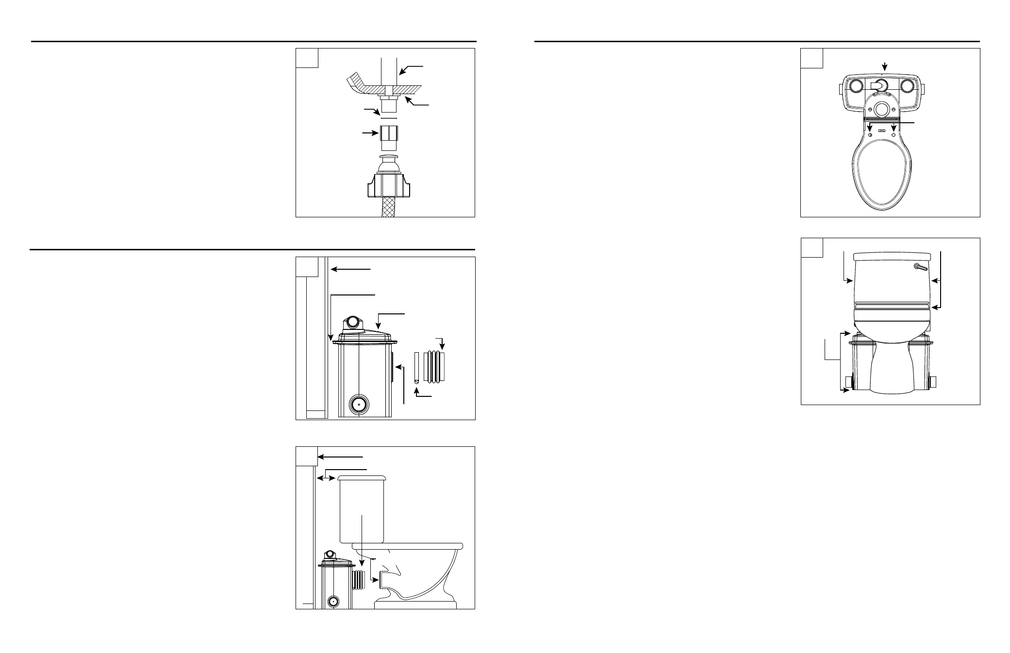
EXPOSED PUMP UNIT INSTALLATION
1. Position the grinder/tank unit a minimum of 1/8" from
the wall with the inlet facing forward. Attach the rubber
coupling to the inlet using the worm drive clamp provided.
IL1740
Inlet
Wall
Grinder
Pump Unit
1/8 in.
Minimum
Rubber
Coupling
Clamp
3. Connect the water supply line to the ballcock shank
that extends below the toilet tank by tightening the
plastic adapter with rubber washer over the end of the
ballcock shank.
CAUTION: Do not overtighten. Ballcock shank may
split and void the warranty.
WATER SUPPLY HOOkUP
Ballcock
Toilet
Tank
Rubber Washer
Plastic Adapter
2. Place the toilet in front of grinder/tank unit; aligning the
discharge of the toilet with the inlet of the grinder/tank unit.
Check to be sure that the rubber coupling will bridge the
gap adequately for final installation. The toilet tank should
be a minimum of 1/2 in. from the wall.
CAUTION: Do not connect rubber coupling to toilet at this
time.
IL1741
Grinder
Unit
Inlet
Toilet Discharge
1/2 in. Minimum
Wall
3. Lightly mark the locations of the grinder/tank unit, toilet
and closet screw set locations on the floor.
Grinder Pump Unit Location
Closet
Screw Set
Locations
3
1
2
3
EXPOSED PUMP UNIT INSTALLATION
4. Lightly mark the wall with the height of the grinder/tank
unit and the bottom and sides of the toilet tank to prevent
interference from pipe runs during pipe installation.
Remove the toilet from the grinder/tank unit and set it
aside until piping is installed.
Grinder/
tank unit
Toilet Tank Bottom and Sides
IL1743
4