Tapped chamber vents, Diaphragm replacement, Reassembly after service – SANDPIPER W15 User Manual
Page 4: Warranty, Warning
7/04 520-150-000
Models W09 & W15 Page 4
TAPPED CHAMBER VENTS
The chamber vent at the top of each outer chamber (see Figure 5) is used to
purge any entrapped air that might accumulate in the chamber. Entrapped air
could cause unbalanced cycling or loss of prime. The gate valve with 1/2" NPT
(12.7mm) threads accomodates a hose or pipe, to vent accumulated air and
fluid back to the liquid source. Ends of the hose or pipe must be submerged in
the liquid being pumped. Tying the pump sides together into a common hose
only moves the air from side to side.
When air is purged, pumped product will discharge from the hose. When
this occurs, close the gate valve and continue normal operation. The valves
may be left partially open, but pump performance will decrease. The tapped
chamber vents can also be used to flush the chambers between uses.
DIAPHRAGM REPLACEMENT
Diaphragms are in-line accessible for service, without disturbing the suction
and discharge flanges. To access the diaphragm, remove the eight (8) locking
knobs around the diaphragm chamber. Remove the locking knobs at the
manifold elbow connections. The housing assembly will pull off. Diaphragms
can now be inspected or replaced. Clear all foreign matter from behind the
diaphragm before reassembling.
REASSEMBLY AFTER SERVICE
To reassemble the pump, begin with the diaphragm assembly. Stack the
wear pad onto the stud of the outer plate. Next, put the diaphragm on to the
stud, with the natural bulge toward the outer plate. Place the inner plate onto
the stud.
Align the five (5) hexhead capscrews and washers through the inner plate,
diaphragm and wear pad, into the outer plate (See Figure 6). Tighten the
capscrews alternately, side to side and corner to corner, use 242 Loctite and
torque to 190 in/lbs. Place the bumper onto the diaphragm rod.
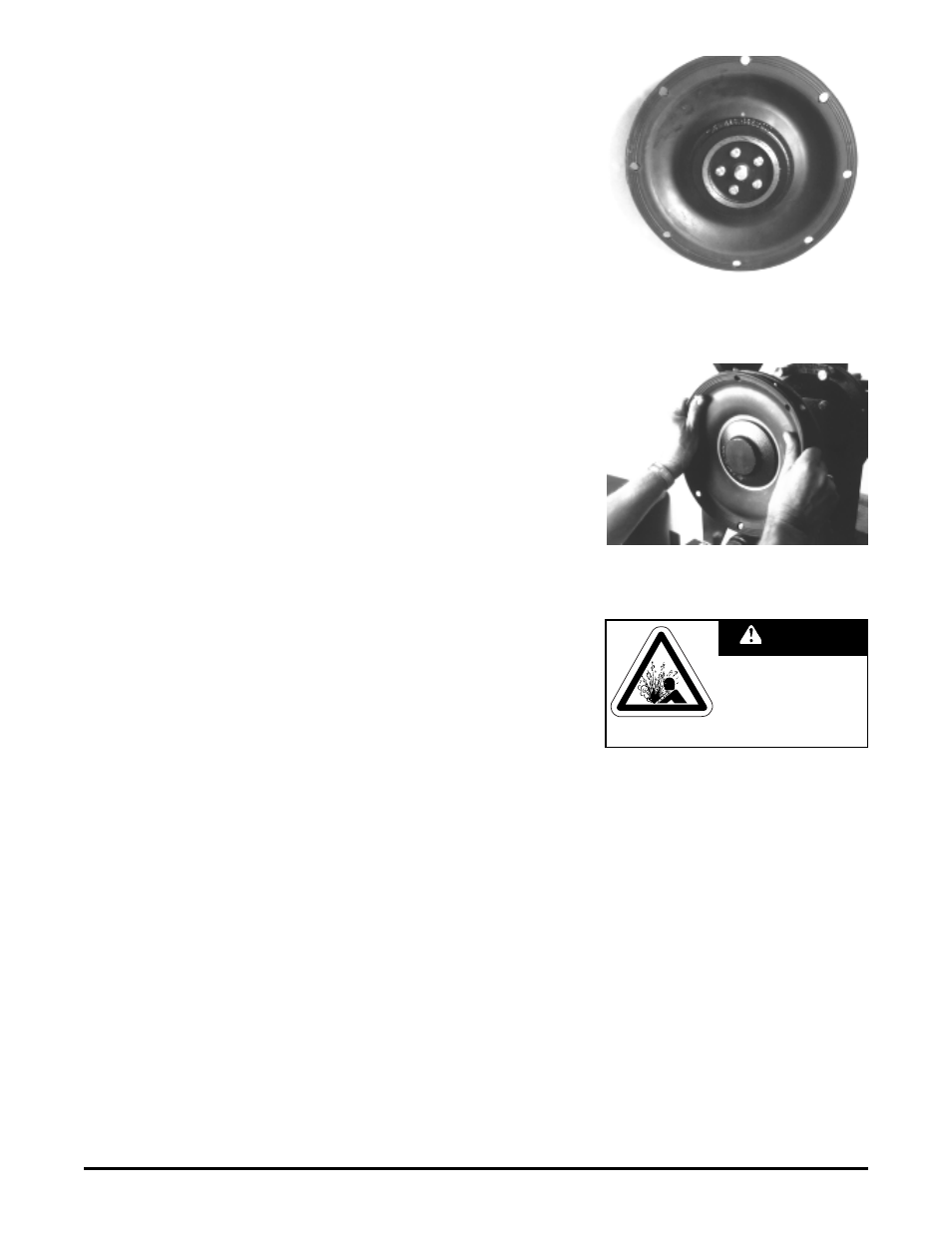
Once the diaphragm assembly is made, thread the stud (from the outer
plate side) into the diaphragm rod. Use Neverseize
®
or equivalent anti-galling
thread lubricant on threads. Turn the assembly onto the rod until it bottoms out,
and the eight (8) holes around the outside of the diaphragm line up with those
on the outer chamber rim (See Figure 7). Back-off tightening as required for
alignment. Reassemble the other side of the pump in the same way. Tighten all
locking knobs to secure the outer chamber to the inner chamber. Tighten all
knobs alternately, side to side and corner to corner.
WARRANTY
This pump is warranted for a period of five years against defective material
and workmanship. Failure to comply with the recommendations stated in this
manual voids all factory warranty.
©2004 Warren Rupp, Inc. All rights reserved.
®Warren Rupp, SANDPIPER and Tranquilizer are registered tradenames of Warren Rupp, Inc.
®Neverseize is a registered tradename of Loctite
Printed in U.S.A.
Figure 6: Align hexhead capscrews and tighten
Figure 7: Align diaphragm holes with chamber
holes
This pump is pressurized
internally with air pressure
during operation. Always
make certain that all bolting
is in good condition and that
all of the correct bolting is
reinstalled during assembly.
WARNING