Air inlet & priming, Air valve lubrication, Air exhaust – SANDPIPER W15 User Manual
Page 2: Between uses, Check valve inspection & clean-out, Check valve replacement
7/04 520-150-000
Models W09 & W15 Page 2
AIR INLET & PRIMING
For start-up, open an air valve approximately ½" to ¾" turn. After the unit primes,
an air valve can be opened to increase flow as desired. If opening the valve
increases cycling rate, but does not increase flow rate, cavitation has occurred, and
the valve should be closed slightly.
For the most efficient use of compressed air and the longest diaphragm life, throttle
the air inlet to the lowest cycling rate that does not reduce flow.
AIR VALVE LUBRICATION
The air end pilot and distribution valves of this pump are designed to operate
without lubrication. However, if poor quality compressed air is interfering with valve
shifting, lubrication may enhance operation. A small amount of non-detergent
lightweight oil (SAE 10 wt. maximum) added at the air inlet port, or the addition of a
Warren Rupp FRL unit (filter/regulator/lubricator) will help the pump operate. If the
air supply is contaminated, dirty, or excessively wet, an air dryer will remove most
water and impurities.
AIR EXHAUST
If a diaphragm fails, the pumped liquid or fumes can enter the air end of the pump,
and be exhausted into the atmosphere. When pumping hazardous or toxic materials,
pipe the exhaust to an appropriate area for safe disposition.
This pump can be submerged if materials of construction are compatible with the
liquid. The air exhaust must be piped above the liquid level. Piping used for the air
exhaust must not be smaller than 1" (2.54 cm). Reducing the pipe size will restrict air
flow and reduce pump performance. When the product source is at a higher level
than the pump (flooded suction), pipe the exhaust higher than the product source to
prevent siphoning spills.
Freezing or icing-up of the air exhaust can occur under certain temperature and
humidity conditions. Use of an air dryer should eliminate most icing problems.
BETWEEN USES
When used for materials that tend to settle out or transform to solid form, the pump
should be completely flushed after each use, to prevent damage. Product remaining
in the pump between uses could dry out or settle out. This could cause problems with
valves and diaphragms at re-start. In freezing temperatures, the pump must be
drained between uses in all cases.
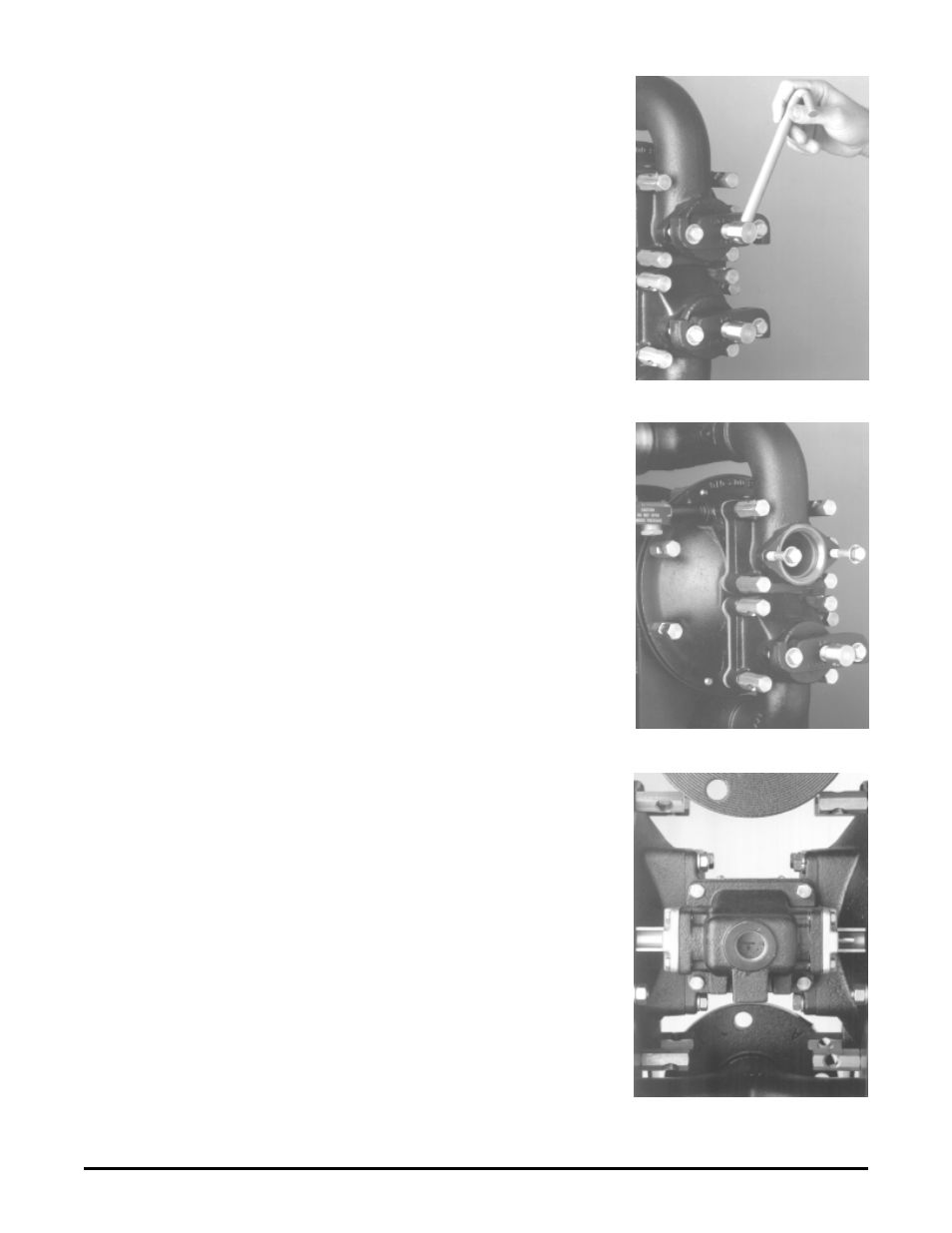
CHECK VALVE INSPECTION & CLEAN-OUT
This pump has replaceable flap-type check valves on suction and discharge of
both outer chambers. A special wrench (See Figure 1.) is provided with each pump.
With it, all fasteners (locking knobs) securing the chambers and valves can be
removed. This allows quick and easy access to all four check valves. A standard ¾"
socket wrench can also be used to loosen locking knobs.
This wastewater pump is designed to handle small and large solids, up to nearly
inlet size; dry sludge; and stringy materials. Solids may occasionally become lodged
between the flap valve and seat. By loosening one locking knob holding the cover
plate yoke, the flap valve is accessible to dislodge debris. (See Figure 2.) This also
allows the insertion of a water hose to flush the outer chambers. Flush the pump by
opening all valve covers (note Caution on Page 1) and allowing water to flow in the
top and out the bottom port on each side of the pump.
CHECK VALVE REPLACEMENT
To replace the check valves, remove the four (4) 3/8" hex nuts. When removed,
the flange on the suction side carries the valve and seat as an assembly. On the
discharge side, the valve and seat will remain with the diaphragm housing. If parts
are being replaced, remove the self-locking nuts to gain access. The large rivet
head on the valve faces toward the seat. Replace the hinge pad and retainer if wear
is evident. Valves must sit flat against the seat. Adjust the fit by tightening the 3/8"
hex nuts.
Use caution when reassembling check valves. The flap valves are designed for
some preload over the retainer hinge pad. This is to insure proper face contact with
the seat. After all parts are in place, tighten the lock nuts on the assembly. Visual
inspection should show the seat and valve face fitting together without a gap. This
fit is important for dry priming. Once primed, the valves will function normally under
differential pressure.
Figure 1: Loosening locking knobs
Figure 2: Check valve clean out
Figure 3: Air distribution valve