Externally serviceable main air distribution valve, Pilot valve, Pilot valve actuator – SANDPIPER W15 User Manual
Page 3: Manual valve override, Caution
7/04 520-150-000
Models W09 & W15 Page 3
EXTERNALLY SERVICEABLE
MAIN AIR DISTRIBUTION VALVE
The sleeve and spool set is located in the valve body, which is held onto the
intermediate bracket by four (4) capscrews. Loosening the four (4) hex head
capscrews allows the valve body to drop out of place (See Figure 3).
Once the valve body is off the pump, remove the four capscrews on the endcap to
inspect the spool and sleeve set. The spool of the air distribution valve is closely
sized to the sleeve. The spool must slide freely in the sleeve. Accumulation of dirt
and contaminants may prevent the spool from moving freely. It may stick in a position
that prevents the pump from cycling.
The plungers (visual stroke indicator) are locked in place on each end of the brass
spool. Before removal, mark the spool and the sleeve, so the spool can be
reassembled in the same end from which it was removed. A spring will be on one
side only, within the spool cavity. The plungers in the spool slide through a brass
bushing and o-ring in the cap.
Clean all parts before reassembly. Use a safety solvent and air oil to keep the
parts from oxidizing. Any nicks on the spool should be removed with a fine stone or
crocus cloth.
When removing the stainless steel sleeve, carefully press it out of the body,
preferably using an arbor press. Reinstall it into the body until it bottoms out against
the opposite endcap and bumper. Use new o-rings when reinstalling and apply a
light coating of grease or O-ring lube before placing in the valve body.
Reinstall the bumper(s), spring, and new gaskets. Tighten the four capscrews to
eliminate air leakage. Reinstall the body on the intermediate bracket with new
gaskets.
PILOT VALVE
The pilot valve assembly is accessed by removing the main air distribution valve
body from the pump and lifting the pilot valve body out of the intermediate housing.
Most problems with the pilot valve can be corrected by replacing the O-rings.
Always grease the spool prior to inserting it into the sleeve. If the sleeve is removed
from the body, reinsertion must be at the chamfered side. Grease the o-rings to slide
the sleeve into the valve body. Securely insert the retaining ring around the sleeve.
When reinserting the pilot valve, push both plungers (located inside the intermediate
bracket) out of the path of the pilot valve spool ends to avoid damage.
PILOT VALVE ACTUATOR
Bushings for the pilot valve actuators are threaded into the intermediate bracket
from the outside. The plunger may be removed for inspection or replacement. First
remove the air distribution valve body and the pilot valve body from the pump. The
plungers can be located by looking into the intermediate. It may be necessary to use
a fine piece of wire to pull them out. The bushing can be turned out through the inner
chamber by removing the outer chamber assembly. Replace the bushings if pins
have bent.
MANUAL VALVE OVERRIDE
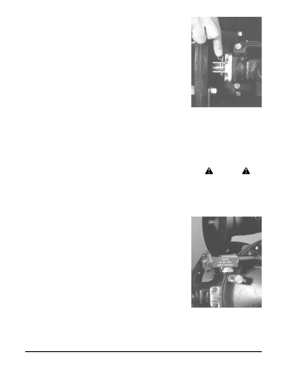
As the pump shifts, the rods from the main air valve move through the endcap. A
rod on the manual override (see Figure 4) can be locked to one side. A pin is provided
to do so. If the rod is on the left, the left side of the pump is on a discharge stroke.
When the pump is cycling, keep fingers away from the override rod and pump
casting. A shield is installed in this area for protection.
By locking the air valve to one side, air cannot flow through the pump, and the
pump will not shift. Use extreme caution when opening clean-out ports. Vent both air
and fluid pressure in the pump and system, prior to opening.
The manual override can also be used to move air through the pump, at low
pressures, to clear blockages. Typically, about 15 psi (1 bar) of air is all that can be
applied to the pump by manually moving the override rods. The valve override can
also be helpful when checking through the troubleshooting points mentioned
elsewhere in this manual.
Figure 5: Chamber vent
Figure 4: Locking pin
CAUTION
Locking pin must be removed before
operation.