Operation, Keypad and display operation, B-3 keypad and display description – Lincoln Electric IM586 STT-10 Head & Controls User Manual
Page 20: Power-down save, Operation keys
B-3
OPERATION
B-3
Keypad and Display Description
Keypad - Eight key, membrane type with "snap" tac-
tile feel and embossed domes. Long life design.
Spatter resistant surface.
Displays - Two digital LED displays with .56" (14.2
mm) character height. Top (3-1/2 digit) displays
Preset Peak and Background Current in amps and
also displays all timers in seconds. Bottom (4 digit)
displays preset wire feed speed in IPM, or m/m, and
acceleration selection.
NOTE: The display of Preset Peak and Background
Current may vary by ± 5% of the set value between
the STT-II and the STT-10.
Indicator Lights - Extra bright red LEDs for viewing
at almost any angle. Always indicate the feeder and
procedure selected, trigger mode being used and
function or timer being displayed.
Rotating Encoders - Knob controls increase or
decrease settings of current and wire feed speed.
(initially factory set to minimum) Alternately, the top
encoder adjusts timer settings and bottom selects
acceleration settings when selected for these parame-
ters to be displayed.
Power-Down Save
Power to the STT-10 is supplied and controlled from
the power source. The STT-10 automatically senses
the loss of power when the power source is turned off.
Dual procedure settings, including; trigger mode, cold
feed speed, Run-in and weld speed and current,
timers ranges and acceleration are automatically
saved when power is removed. This feature does not
require batteries and when power is restored it will
automatically return all settings to the state they were
in when power was removed. The operator may over-
write any or all of these settings following power up
recall.
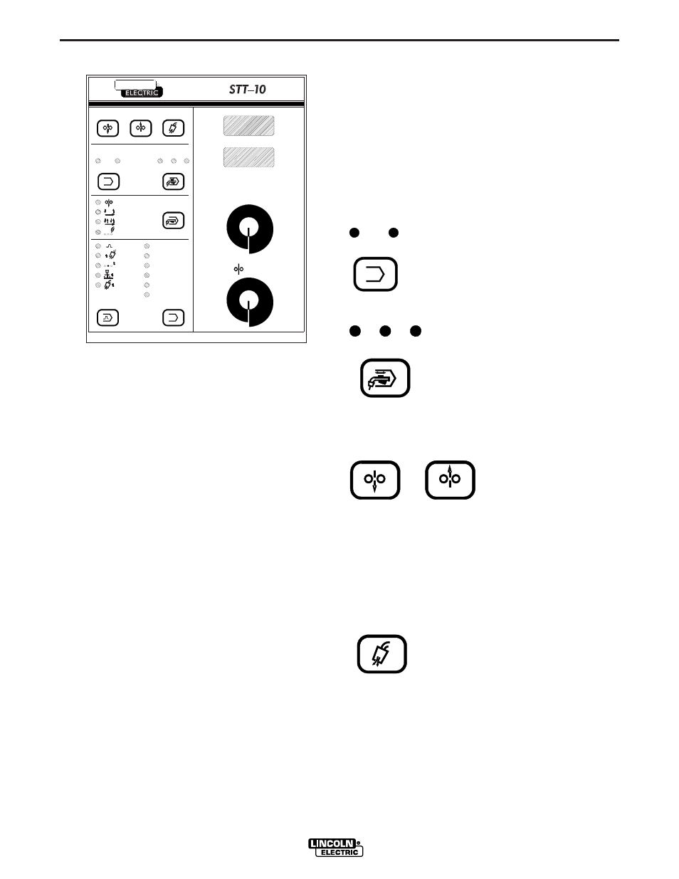
Operation Keys
Current Lights - Indicates whether the
top display controls peak current or
background current setting.
Procedure Lights - Indicate which
procedure (A or B) is selected. The
Procedure select key selects A or B, or
if REMOTE Light is selected, the pro-
cedure selection light is controlled by
connection of an optional Dual
Procedure gun switch (K683-1, -2).
Cold Feed Keys - energize
the wire feeder but not the
power source or gas sole-
noid valve. Cold Feed
Forward speed is factory
set at 200 IPM, but is adjustable with WFS encoder
knob and displayed on WFS display (with ”Cld” shown
on the Voltage display) only while pressing Cold Feed
Forward, and the last speed set is stored in memory
for the next cold feeding, unless changed in Cold
Feed trigger mode (see following section). Cold Feed
Reverse retracts wire at a fixed 80 IPM speed which is
not adjustable.
Gas Purge key - energizes the gas
solenoid valve but not the wire feeder or
power source.
STT-10
KEYPAD AND DISPLAY OPERATION
SPOT
PEAK MAX
CURRENT
SPOT
PREFLOW
1
RUN-IN
WFS
PEAK MIN
BACKGROUND MAX
CONTROL
WIRE FEED SPEED
G3152
BURNBACK
POSTFLOW
GAS PURGE
FORWARD
COLD FEED
2
BACKGROUND MIN
WFS MAX
WFS MIN
RANGE
THE LINCOLN ELECTRIC COMPANY CLEVELAND, OHIO U.S.A.
COLD FEED
REVERSE
CURRENT
BACKGROUND
PROCEDURE
PEAK
TRIGGER
COLD FEED
2-STEP STD
4-STEP LOCK
WFS
A
A
B
A
REMOTE
R
LINCOLN
A
CURRENT
BACKGROUND
PEAK
A
GAS PURGE
FORWARD
COLD FEED
REVERSE
COLD FEED
A
B
PROCEDURE
REMOTE