Operation, B-31, Limit setting – Lincoln Electric IM915 POWER FEED 10M SINGLE WIRE FEEDER User Manual
Page 53
B-31
OPERATION
B-31
POWER FEED
®
10M SINGLE WIRE FEEDER
6. OPTIONAL DUAL PROCEDURE/MEMORY
PANEL OPERATION
The Dual Procedure/Memory Panel performs three
functions:
• Weld procedure selection
• Memory save and recall
• Limits setting
There are two procedure memories (A and B) and six
user memories (1-6).
Procedure Memory vs. User Memory
Procedure memory is used while welding. Changes to
the weld procedure (WFS, voltage, arc control, etc.)
immediately change the contents inside the selected
procedure memory. Procedure memory saving is
done automatically.
User memories work by copying the weld procedure
from one of the six memories into either the A or B
procedure. Weld procedures are saved into the mem-
ories only when the operator chooses.
Using Procedure Memories
Procedure memories can be selected by choosing
either "A" or "B" procedure directly with the memory
panel, or by selecting "GUN" and using a dual proce-
dure gun to select between procedure "A" and "B".
When selecting procedures with the gun switch, "A" or
"B" will flash to show which procedure is active.
HOLD 2 SECONDS TO SAVE
PROCEDURE
MEMORY
A
GUN
B
1
4
2
5
3
6
M
M
HOLD 2 SECONDS TO SAVE
PROCEDURE
MEMORY
A
GUN
B
1
4
2
5
3
6
M
M
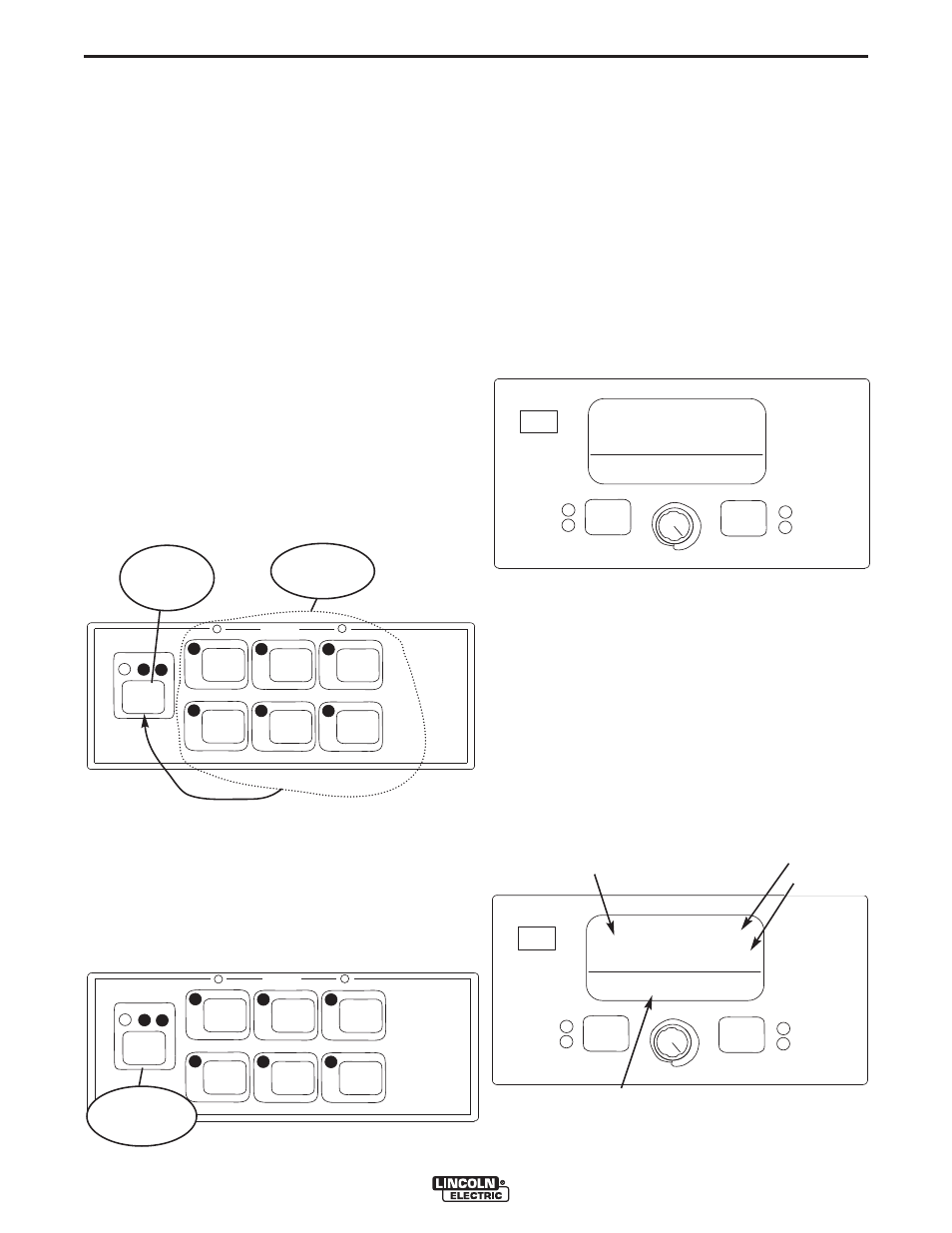
PROCEDURE
MEMORY
PRESS TO
SELECT
PROCEDURE
USER
MEMORIES
LIMIT SETTING
Each user memory can be optionally configured to limit
the userʼs range of control over some user interface set-
tings. By default, user limits are not enabled. To set lim-
its for a selected memory, first select a weld mode and
perform a memory save. Next, press and hold the mem-
ory button for five seconds. Release the memory button
when the memory LED begins to blink rapidly and the
Mode Select Panel displays indicate "Set Limits".
If the passcode has been set to a value other than zero,
the user will be prompted to enter it. If the passcode is
zero, the Mode Select Panel will immediately display the
Limit Setup menu and the SETUP LED will illuminate:
The above example shows a wire mode, constant current
weld modes would show "Weld Amps" rather than "Weld
WFS".
There are four items displayed on each Limit Setup
screen. The long alphanumeric display shows the
selected attribute (e.g. Weld WFS,Volts, etc.). The short
alphanumeric displays show the selected attributeʼs high
and low user limits. The 7-segment displays show the
value that is copied to procedure memory when a memo-
ry recall is performed.
START OPTIONS
END OPTIONS
HI = 220
LO = 180
SET
SETUP
IR PORT
WELD WFS
WAVEFORM CONTROL TECHNOLOGY
200
WELD MODE
ARC CONTROL
START OPTIONS
END OPTIONS
HI = 220
LO = 180
SET
SETUP
IR PORT
WELD WFS
WAVEFORM CONTROL TECHNOLOGY
200
WELD MODE
ARC CONTROL
Memory Value
Attribute
High Limit
Low Limit