Installation, Safety precaution, Caution – Lincoln Electric IM915 POWER FEED 10M SINGLE WIRE FEEDER User Manual
Page 10
A-2
INSTALLATION
POWER FEED
®
10M SINGLE WIRE FEEDER
A-2
SAFETY PRECAUTION
LOCATION
• The POWER FEED
®
10M Single Wire Feeder has
an IP21 rating, suitable for indoor use.
• The POWER FEED
®
10M Single Wire Feeder
should be operated in a substantially upright posi-
tion.
• Do not submerge the POWER FEED
®
10M Single
Wire Feeder.
• The POWER FEED
®
10M Single Wire Feeder is not
suitable for stacking.
Locate the POWER FEED
®
10M Single Wire Feeder
away from radio controlled machinery. The normal
operation of the POWER FEED
®
10M Single Wire
Feeder may adversely affect the operation of RF con-
trolled equipment, which may result in bodily injury or
damage to the equipment.
ELECTRIC SHOCK can kill.
• Only qualified personnel should
perform this installation.
• Turn off the input power to the
power source at the disconnect
switch or fuse box before working
on this equipment. Turn off the
input power to any other equipment
connected to the welding system at
the disconnect switch or fuse box
before working on this equipment.
• Do not touch electrically hot parts.
----------------------------------------------------------------------------------------
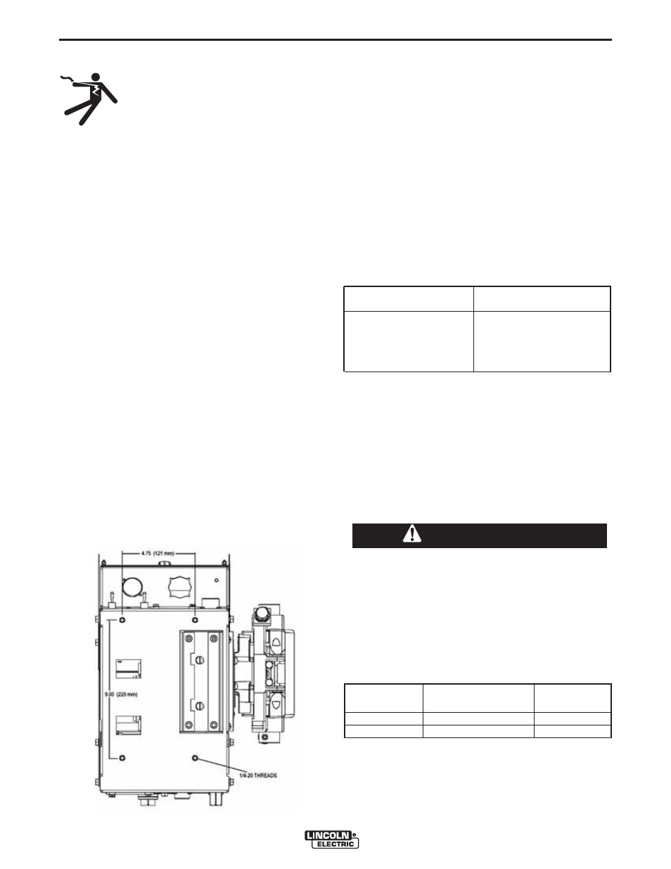
FIGURE A.1
MOUNTING
Wire Drive Mounting (See Figure A.1)
The wire drive may be mounted by using the four
holes on the bottom. Because the feed plate and
gearbox are electrically "hot" when welding, make cer-
tain the parts do not contact the any structure or per-
son.
Mount the wire drive with the drive rolls in the vertical
plane to prevent dirt from collecting in the wire drive.
Angle the drive and feed plate to prevent sharp bends
in the gun and cable and incoming wire.
WELD CABLE SIZING
Minimum work and electrode cables sizes are as follows:
TABLE A.1
(Current (60% Duty Cycle) MINIMUM COPPER
WORK CABLE SIZE AWG
Up To-100 Ft. Length (30 m)
400 Amps
2/0 (67 mm2)
500 Amps
3/0 (85 mm2)
600 Amps
3/0 (85 mm2)
WELD CABLE CONNECTION
Connect a work lead of sufficient size and length (Per
Table A.1) between the proper output terminal on the
power source and the work. Be sure the connection to
the work makes tight metal-to-metal electrical contact.
To avoid interference problems with other equipment
and to achieve the best possible operation, route all
cables directly to the work or wire feeder. Avoid
excessive lengths and do not coil excess cable.
When using an inverter type power source like the
Power Waves
®
, use the largest welding (electrode
and work) cables that are practical. At least 2/0
copper wire - even if the average output current
would not normally require it. When pulsing, the
pulse current can reach very high levels. Voltage
drops can become excessive, leading to poor
welding characteristics, if undersized welding
cables are used.
------------------------------------------------------------------------
For Electrode
Connect the
Connect the
Polarity:
Electrode lead to
work lead to
Positive
Positive Stud
Negative
Negative
Negative Stud
Positive Stud
For additional Safety information regarding the elec-
trode and work cable set-up, See the standard "SAFE-
TY INFORMATION" located in the front of the
Instruction Manuals.
CAUTION