Installation, Warning – Lincoln Electric IM626 Mobiflex 200-M Lamp Kit User Manual
Page 12
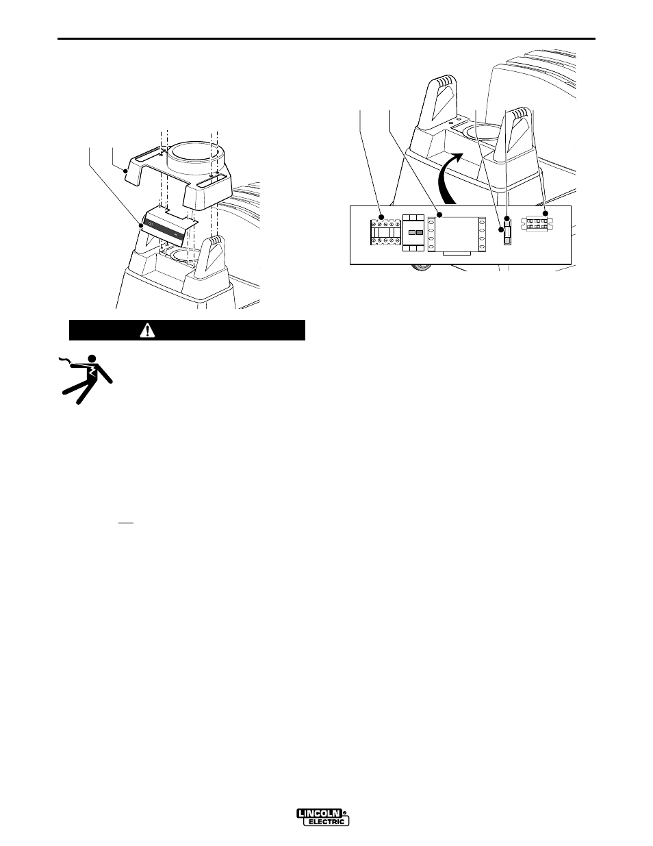
Loosen the four screws of the cover (Fig. 8, Item B),
lift the cover around the arm and turn it 180 degrees,
and allow it to rest on the filter cover. Remove the
control cover (Fig. 8, Item A), secured by four screws
as shown. Route the 13 ft. connecting cable through
the grommet in the control cover (cut an X as before).
ELECTRIC SHOCK can kill.
• Do not touch electrically live parts such
as internal wiring.
• Turn the input power off at the fuse box
before working on this equipment.
• Have a qualified person install and ser-
vice this equipment.
------------------------------------------------------------------------
Note: To insert conductors in Terminal Block, push in
on front opening with small screwdriver, and insert
conductor into corresponding top opening.
Note: GN is not the same potential as Ground.
MOUNTING THE TRANSFORMER RELAY KIT
When installing a K1669-1 or K1669-3 Lamp Kit on
a K1653-1 Mobiflex 200-M:
Note: If the control panel has the Contactor,
Transformer, Fuseholder/Fuse, and Terminal Block
already installed (as in Fig. 9), skip to the next step
“Making the final connections at the Control Panel.”
Use the seven supplied screws to mount the pieces of
the Transformer Relay Kit in the Control Panel of the
Mobiflex unit as shown in Figure 9.
Use the two smaller screws to mount the terminal
block (E), one of the larger screws to mount the fuse
holder (C), and the four remaining large screws to
mount the transformer (B). Mount the Contactor (A) on
the DIN rail next to the Starter/Overload.
The mounting points have been marked on the mount-
ing surface of the control panel.
Note: Make sure there are no wires routed between
the Contactor and Starter/OL, as this may interfere
with the proper positioning of the Starter/OL buttons
when replacing the Control Cover.
Have a qualified electrician make the connections
according to the wiring diagram in the back of this
manual. Reference wiring diagrams for “K1653-1
Mobiflex 200-M” and “Mobiflex 200-M with Lamp
Option and Arc Sensor” in the back of this manual.
Note: The (2) fan motor wires must be moved from
the top of the Starter/OL to the bottom of the
Contactor. Reference the wiring diagram in the back
of this manual for details.
Loop any extra cable inside the control box. Verify that
the two ground wires are connected to the tabs on the
inside of the Control Cover. Line up the Start and Stop
buttons on the Starter/OL with the proper holes in the
control cover, and replace the control cover; secure
with the four screws. Replace the large cover over the
handles.
MAKING THE FINAL CONNECTION AT THE
CONTROL PANEL
When installing a K1706-1 or K1706-2 Work Lamp
on a K1653-2 Mobiflex 200-M:
Remove the jumper on the terminal block. Connect
the leads of the 13 ft. connecting cable according to
color (WH, BN, GN). Loop any extra cable inside the
control box. Replace the control cover and large cover
over the handles.
A
B
Fig. 8
A
B
C
D
E
Fuse
Terminal Block
Fuse Holder
Contactor
Starter/OL
Transformer
Fig. 9
WARNING
A-5
INSTALLATION
LAMP OPTIONS FOR MOBIFLEX 200-M
A-5