Operation, Warning – Lincoln Electric IM733 LN-15 WIRE FEEDER User Manual
Page 18
B-6
OPERATION
B-6
LN-15 ACROSS THE ARC MODEL
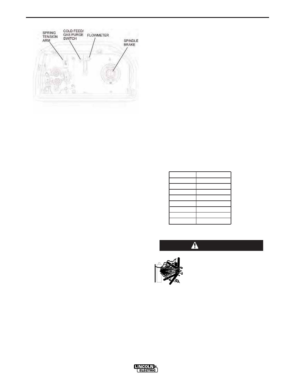
SPRING TENSION ARM
The spring tension arm sets the clamping pressure of
the drive rolls on the electrode. The optimum pressure
varies with the type of wire, wire diameter, surface
conditions, lubrication and hardness. As a general
rule, hard electrodes like solid stainless electrodes
may require greater pressure and softer electrodes
like aluminum may use less pressure.
To set the spring tension arm
•
Turn the knob until it is approximately at the #3
mark.
•
Press the end of the gun against a solid object that
is electrically isolated from the welder output and
cold feed for several seconds.
•
If the wire "birdnests", jams or breaks at the wire
drive than the idle roll pressure is too great. Loosen
the pressure arm by about a 1/2 turn., run new wire
through the gun, and repeat the above steps.
•
If the drive rolls slipped on the wire, loosen the
adjustment knob on the feed plate and the gun and
cable assembly forward about 6" (15cm). A slight
waviness will be visible (it will be more visible with
smaller or softer electrodes.) If there are no waves
in the wire, tighten the knob 1/4 turn, reinstall the
gun and cable assembly and repeat the above
steps.
COLD FEED/GAS PURGE SWITCH
Inside the LN-15 is a
“
center-off
”
momentary toggle
switch for Cold Feed/Gas Purge.
When held in the UP position, the wire drive will feed
electrode but neither the power source nor the gas
solenoid will be energized. When cold feeding, the
feed speed is the same as the welding wire feed
speed. The wire feed speed may be adjusted by rotat-
ing the WFS knob on the front of the LN-15.
INTERNAL CONTROLS
(Figure B.2)
When the toggle switch is held in the DOWN position,
the gas solenoid valve is energized but neither the
power source nor the drive motor will be energized.
While the Gas Purge button is activated, the flow rate
of the Shielding gas can be adjusted. See the
“
Flow
meter
“
section below.
SPINDLE BRAKE
Adjust the spindle brake tension to allow the spool to
spin freely, yet have enough resistance for little or no
overrun when wire feeding is stopped.
FLOW METER
The flowmeter shows the flow rate of shielding gas
and has a valve to adjust the flow. It is calibrated in
Standard Cubic Feet per Hour (SCFH) for CO2, Ar,
and CO2/Ar blends.
The flow rate may be adjusted by turning the valve at
the top of the meter. Most weld procedures require
25-40 scfh (11.8 - 18.9 Liters/Hour) for sufficient
shielding gas coverage. Gun angle, nozzle diameter,
joint configuration and wind conditions may effect the
amount of shielding gas required. To convert (SCFH)
to Liters/Hour multiply SCFH value by .472.
SCFH
Liter/Hour
10
4.7
20
9.4
30
14.2
40
18.9
50
23.6
60
28.3
70
33.1
80
37.8
SHIELDING GAS CONNECTION
CYLINDER may explode if
damaged.
•
Keep cylinder upright and
chained to support.
•
Keep cylinder away from areas where it may be
damaged.
•
Never lift welder with cylinder attached.
•
Never allow welding electrode to touch cylinder.
•
Keep cylinder away from welding or other live
electrical circuits.
-----------------------------------------------------------------------
WARNING